
Rating:
Information injection-pump assembly
BOSCH
9 400 618 479
9400618479
ZEXEL
106873-7243
1068737243
MITSUBISHI
ME093918
me093918
Cross reference number
BOSCH
9 400 618 479
9400618479
ZEXEL
106873-7243
1068737243
MITSUBISHI
ME093918
me093918
Zexel num
Bosch num
Firm num
Name
106873-7243
9 400 618 479
ME093918 MITSUBISHI
INJECTION-PUMP ASSEMBLY
8DC9 K
8DC9 K
Calibration Data:
Adjustment conditions
Test oil
1404 Test oil ISO4113 or {SAEJ967d}
1404 Test oil ISO4113 or {SAEJ967d}
Test oil temperature
degC
40
40
45
Nozzle and nozzle holder
105780-8250
Bosch type code
1 688 901 101
Nozzle
105780-0120
Bosch type code
1 688 901 990
Nozzle holder
105780-2190
Opening pressure
MPa
20.7
Opening pressure
kgf/cm2
211
Injection pipe
Outer diameter - inner diameter - length (mm) mm 8-3-600
Outer diameter - inner diameter - length (mm) mm 8-3-600
Overflow valve
131425-0220
Overflow valve opening pressure
kPa
157
123
191
Overflow valve opening pressure
kgf/cm2
1.6
1.25
1.95
Tester oil delivery pressure
kPa
255
255
255
Tester oil delivery pressure
kgf/cm2
2.6
2.6
2.6
Direction of rotation (viewed from drive side)
Right R
Right R
Injection timing adjustment
Direction of rotation (viewed from drive side)
Right R
Right R
Injection order
1-2-7-3-
4-5-6-8
Pre-stroke
mm
3.9
3.85
3.95
Beginning of injection position
Governor side NO.1
Governor side NO.1
Difference between angles 1
Cyl.1-2 deg. 45 44.5 45.5
Cyl.1-2 deg. 45 44.5 45.5
Difference between angles 2
Cal 1-7 deg. 90 89.5 90.5
Cal 1-7 deg. 90 89.5 90.5
Difference between angles 3
Cal 1-3 deg. 135 134.5 135.5
Cal 1-3 deg. 135 134.5 135.5
Difference between angles 4
Cal 1-4 deg. 180 179.5 180.5
Cal 1-4 deg. 180 179.5 180.5
Difference between angles 5
Cal 1-5 deg. 225 224.5 225.5
Cal 1-5 deg. 225 224.5 225.5
Difference between angles 6
Cal 1-6 deg. 270 269.5 270.5
Cal 1-6 deg. 270 269.5 270.5
Difference between angles 7
Cal 1-8 deg. 315 314.5 315.5
Cal 1-8 deg. 315 314.5 315.5
Injection quantity adjustment
Adjusting point
-
Rack position
11.5
Pump speed
r/min
700
700
700
Each cylinder's injection qty
mm3/st.
115
111.5
118.5
Basic
*
Fixing the rack
*
Standard for adjustment of the maximum variation between cylinders
*
Injection quantity adjustment_02
Adjusting point
Z
Rack position
8+-0.5
Pump speed
r/min
430
430
430
Each cylinder's injection qty
mm3/st.
19
16.1
21.9
Fixing the rack
*
Standard for adjustment of the maximum variation between cylinders
*
Injection quantity adjustment_03
Adjusting point
A
Rack position
R1(11.5)
Pump speed
r/min
700
700
700
Average injection quantity
mm3/st.
115
114
116
Basic
*
Fixing the lever
*
Injection quantity adjustment_04
Adjusting point
B
Rack position
R1+0.9
Pump speed
r/min
1100
1100
1100
Average injection quantity
mm3/st.
117
113
121
Fixing the lever
*
Injection quantity adjustment_05
Adjusting point
C
Rack position
R1-0.6
Pump speed
r/min
500
500
500
Average injection quantity
mm3/st.
111
107
115
Fixing the lever
*
Test data Ex:
Governor adjustment
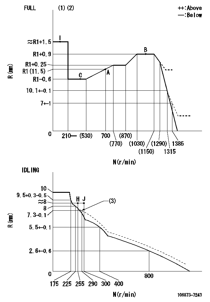
N:Pump speed
R:Rack position (mm)
(1)Torque cam stamping: T1
(2)Tolerance for racks not indicated: +-0.05mm.
(3)Damper spring setting
----------
T1=AC74
----------
----------
T1=AC74
----------
Timer adjustment
(1)Adjusting range
(2)Step response time
(N): Speed of the pump
(L): Load
(theta) Advance angle
(Srd1) Step response time 1
(Srd2) Step response time 2
1. Adjusting conditions for the variable timer
(1)Adjust the clearance between the pickup and the protrusion to L.
----------
L=1-0.2mm N2=800r/min C2=(10deg) t1=2.5--sec. t2=2.5--sec.
----------
N1=750++r/min P1=0kPa(0kgf/cm2) P2=392kPa(4kgf/cm2) C1=10+-0.3deg R01=0/4load R02=4/4load
----------
L=1-0.2mm N2=800r/min C2=(10deg) t1=2.5--sec. t2=2.5--sec.
----------
N1=750++r/min P1=0kPa(0kgf/cm2) P2=392kPa(4kgf/cm2) C1=10+-0.3deg R01=0/4load R02=4/4load
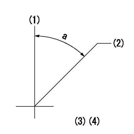
Speed control lever angle
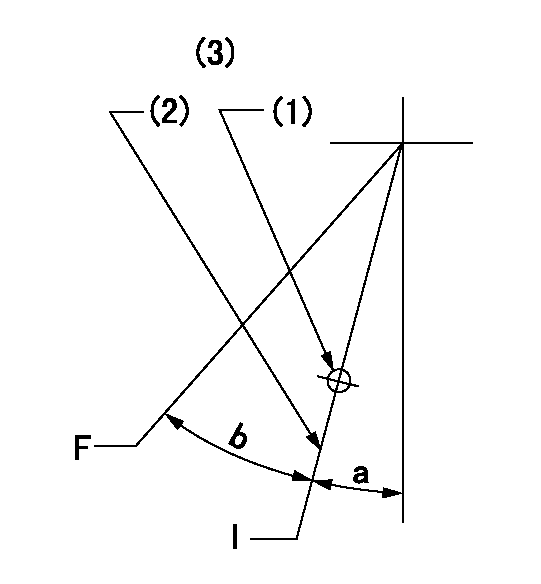
F:Full speed
I:Idle
(1)Use the hole at R = aa
(2)Stopper bolt set position 'H'
(3)Viewed from feed pump side.
----------
aa=37.5mm
----------
a=32deg+-5deg b=(42deg)+-3deg
----------
aa=37.5mm
----------
a=32deg+-5deg b=(42deg)+-3deg
Stop lever angle
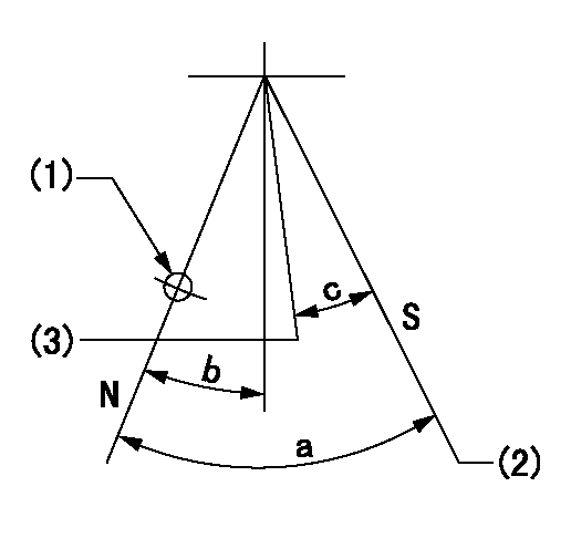
N:Pump normal
S:Stop the pump.
(1)Use the hole at R = aa
(2)Set the stopper bolt so that speed = bb and rack position = cc. (Confirm non-injection.)
(3)Normal engine position (Rack position corresponding to dd)
----------
aa=54mm bb=1100r/min cc=3+-0.3mm dd=17.5mm
----------
a=41deg+-5deg b=5.5deg+-5deg c=(31deg)
----------
aa=54mm bb=1100r/min cc=3+-0.3mm dd=17.5mm
----------
a=41deg+-5deg b=5.5deg+-5deg c=(31deg)
0000001501 MICRO SWITCH
Adjustment of the micro-switch
Adjust the bolt to obtain the following lever position when the micro-switch is ON.
(1)Speed N1
(2)Rack position Ra
----------
N1=335r/min Ra=7.9+-0.1mm
----------
----------
N1=335r/min Ra=7.9+-0.1mm
----------
0000001601 RACK SENSOR

(VR) measurement voltage
(I) Part number of the control unit
(G) Apply red paint.
(H): End surface of the pump
1. Rack sensor adjustment (-0620)
(1)Fix the speed control lever at the full position
(2)Set the speed to N1 r/min.
(If the boost compensator is provided, apply boost pressure.)
(3)Adjust the bobbin (A) so that the rack sensor's output voltage is VR+-0.01.
(4)At that time, rack position must be Ra.
(5)Apply G at two places.
Connecting part between the joint (B) and the nut (F)
Connecting part between the joint (B) and the end surface of the pump (H)
----------
N1=1100r/min Ra=R1(11.5)+0.9mm
----------
----------
N1=1100r/min Ra=R1(11.5)+0.9mm
----------
0000001701 SPEED SENSOR
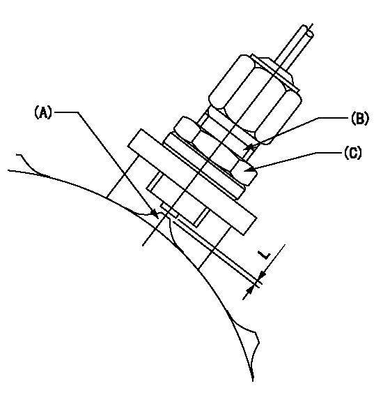
(A) Flyweight projection
(B) Pickup sensor
(c) Lock nut
Speed sensor installation
(1)Install the speed sensor so that the clearance between the sensor and the flyweight projection is L.
(This gap is the gap when the pickup sensor is returned 1 turn from where it contacts the flyweight tooth.)
----------
L=0.8~1mm
----------
----------
L=0.8~1mm
----------
Timing setting
(1)Pump vertical direction
(2)Coupling's key groove position at No 1 cylinder's beginning of injection
(3)B.T.D.C.: aa
(4)-
----------
aa=4deg
----------
a=(50deg)
----------
aa=4deg
----------
a=(50deg)
Have questions with 106873-7243?
Group cross 106873-7243 ZEXEL
Mitsubishi
Mitsubishi
Mitsubishi
Mitsubishi
106873-7243
9 400 618 479
ME093918
INJECTION-PUMP ASSEMBLY
8DC9
8DC9