
Rating:
Information injection-pump assembly
BOSCH
F 019 Z10 648
f019z10648
ZEXEL
106871-8800
1068718800
HINO
220007280A
220007280a
Service parts 106871-8800 INJECTION-PUMP ASSEMBLY:
1.
_
7.
COUPLING PLATE
8.
_
9.
_
11.
Nozzle and Holder
236001651A
12.
Open Pre:MPa(Kqf/cm2)
15.7(160)/21.6(220)
15.
NOZZLE SET
Include in #1:
106871-8800
as INJECTION-PUMP ASSEMBLY
Cross reference number
BOSCH
F 019 Z10 648
f019z10648
ZEXEL
106871-8800
1068718800
HINO
220007280A
220007280a
Zexel num
Bosch num
Firm num
Name
Calibration Data:
Adjustment conditions
Test oil
1404 Test oil ISO4113 or {SAEJ967d}
1404 Test oil ISO4113 or {SAEJ967d}
Test oil temperature
degC
40
40
45
Nozzle and nozzle holder
105780-8140
Bosch type code
EF8511/9A
Nozzle
105780-0000
Bosch type code
DN12SD12T
Nozzle holder
105780-2080
Bosch type code
EF8511/9
Opening pressure
MPa
17.2
Opening pressure
kgf/cm2
175
Injection pipe
Outer diameter - inner diameter - length (mm) mm 8-3-600
Outer diameter - inner diameter - length (mm) mm 8-3-600
Overflow valve
134424-0820
Overflow valve opening pressure
kPa
127
107
147
Overflow valve opening pressure
kgf/cm2
1.3
1.1
1.5
Tester oil delivery pressure
kPa
157
157
157
Tester oil delivery pressure
kgf/cm2
1.6
1.6
1.6
Direction of rotation (viewed from drive side)
Right R
Right R
Injection timing adjustment
Direction of rotation (viewed from drive side)
Right R
Right R
Injection order
1-8-6-2-
7-5-4-3
Pre-stroke
mm
4.8
4.74
4.8
Beginning of injection position
Drive side NO.1
Drive side NO.1
Difference between angles 1
Cal 1-8 deg. 45 44.75 45.25
Cal 1-8 deg. 45 44.75 45.25
Difference between angles 2
Cal 1-6 deg. 90 89.75 90.25
Cal 1-6 deg. 90 89.75 90.25
Difference between angles 3
Cyl.1-2 deg. 135 134.75 135.25
Cyl.1-2 deg. 135 134.75 135.25
Difference between angles 4
Cal 1-7 deg. 180 179.75 180.25
Cal 1-7 deg. 180 179.75 180.25
Difference between angles 5
Cal 1-5 deg. 225 224.75 225.25
Cal 1-5 deg. 225 224.75 225.25
Difference between angles 6
Cal 1-4 deg. 270 269.75 270.25
Cal 1-4 deg. 270 269.75 270.25
Difference between angles 7
Cal 1-3 deg. 315 314.75 315.25
Cal 1-3 deg. 315 314.75 315.25
Injection quantity adjustment
Adjusting point
A
Rack position
9.5
Pump speed
r/min
700
700
700
Average injection quantity
mm3/st.
143.6
141.6
145.6
Max. variation between cylinders
%
0
-2
2
Basic
*
Fixing the lever
*
Injection quantity adjustment_02
Adjusting point
B
Rack position
9.8
Pump speed
r/min
1100
1100
1100
Average injection quantity
mm3/st.
141.1
138.1
144.1
Max. variation between cylinders
%
0
-4
4
Fixing the lever
*
Injection quantity adjustment_03
Adjusting point
C
Rack position
9.6
Pump speed
r/min
900
900
900
Average injection quantity
mm3/st.
143.4
140.4
146.4
Fixing the lever
*
Injection quantity adjustment_04
Adjusting point
D
Rack position
9.5
Pump speed
r/min
500
500
500
Average injection quantity
mm3/st.
148.5
142.5
154.5
Fixing the lever
*
Injection quantity adjustment_05
Adjusting point
E
Rack position
9.1
Pump speed
r/min
1200
1200
1200
Average injection quantity
mm3/st.
123.4
117.4
129.4
Fixing the lever
*
Injection quantity adjustment_06
Adjusting point
F
Rack position
4.2+-0.5
Pump speed
r/min
225
225
225
Average injection quantity
mm3/st.
9.6
6.6
12.6
Max. variation between cylinders
%
0
-15
15
Fixing the rack
*
Timer adjustment
Pump speed
r/min
900
Advance angle
deg.
1.7
1.4
2
Load
3/4
Timer adjustment_02
Pump speed
r/min
1060
Advance angle
deg.
4.75
4.45
5.05
Load
4/4
Remarks
Finish
Finish
Test data Ex:
Governor adjustment
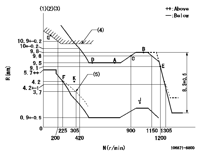
N:Pump speed
R:Rack position (mm)
(1)Lever ratio: RT
(2)Target shim dimension: TH
(3)Tolerance for racks not indicated: +-0.05mm.
(4)Excess fuel setting for starting: SXL
(5)Set the damper spring (after setting the idle spring).
----------
RT=0.8 TH=2.7mm SXL=10.7+-0.1mm
----------
----------
RT=0.8 TH=2.7mm SXL=10.7+-0.1mm
----------
Speed control lever angle
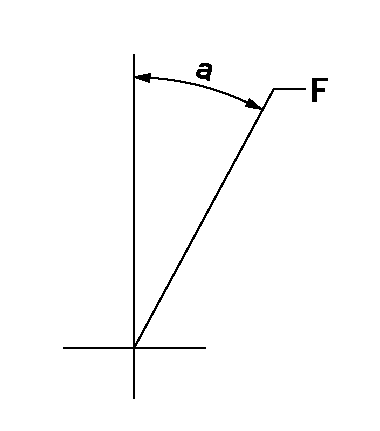
F:Full speed
----------
----------
a=14deg+-5deg
----------
----------
a=14deg+-5deg
0000000901
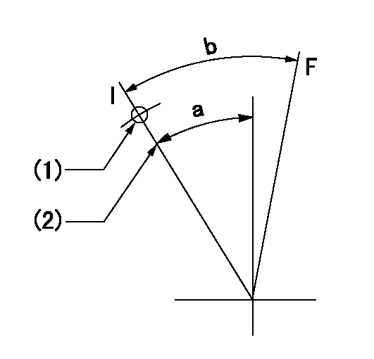
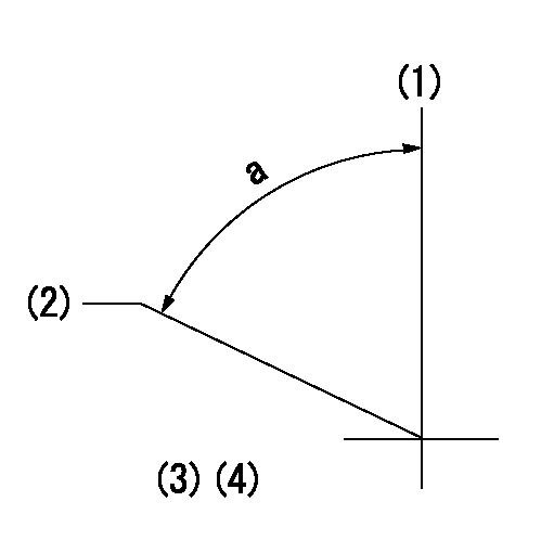
F:Full load
I:Idle
(1)Stopper bolt setting
(2)Use the hole at R = aa
----------
aa=42mm
----------
a=39deg+-5deg b=46deg+-3deg
----------
aa=42mm
----------
a=39deg+-5deg b=46deg+-3deg
Stop lever angle
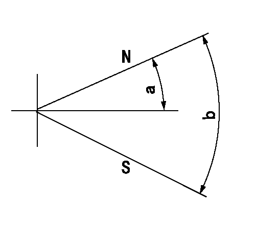
N:Pump normal
S:Stop the pump.
----------
----------
a=46deg+-5deg b=64deg+-5deg
----------
----------
a=46deg+-5deg b=64deg+-5deg
0000001501 RACK SENSOR

(VR) measurement voltage
(I) Part number of the control unit
(G) Apply red paint.
(H): End surface of the pump
1. Rack sensor adjustment (-0620)
(1)Fix the speed control lever at the full position
(2)Set the speed to N1 r/min.
(If the boost compensator is provided, apply boost pressure.)
(3)Adjust the bobbin (A) so that the rack sensor's output voltage is VR+-0.01.
(4)At that time, rack position must be Ra.
(5)Apply G at two places.
Connecting part between the joint (B) and the nut (F)
Connecting part between the joint (B) and the end surface of the pump (H)
----------
N1=1070r/min Ra=9.8mm
----------
----------
N1=1070r/min Ra=9.8mm
----------
Timing setting
(1)Pump vertical direction
(2)Coupling's key groove position at No 1 cylinder's beginning of injection
(3)-
(4)-
----------
----------
a=(80deg)
----------
----------
a=(80deg)