
Rating:
Information injection-pump assembly
ZEXEL
106693-1410
1066931410
ISUZU
1156017400
1156017400
Cross reference number
ZEXEL
106693-1410
1066931410
ISUZU
1156017400
1156017400
Zexel num
Bosch num
Firm num
Name
106693-1410
1156017400 ISUZU
INJECTION-PUMP ASSEMBLY
6RB1 * K
6RB1 * K
Calibration Data:
Adjustment conditions
Test oil
1404 Test oil ISO4113 or {SAEJ967d}
1404 Test oil ISO4113 or {SAEJ967d}
Test oil temperature
degC
40
40
45
Nozzle and nozzle holder
105780-8140
Bosch type code
EF8511/9A
Nozzle
105780-0000
Bosch type code
DN12SD12T
Nozzle holder
105780-2080
Bosch type code
EF8511/9
Opening pressure
MPa
17.2
Opening pressure
kgf/cm2
175
Injection pipe
Outer diameter - inner diameter - length (mm) mm 8-3-600
Outer diameter - inner diameter - length (mm) mm 8-3-600
Overflow valve
134424-1920
Overflow valve opening pressure
kPa
127
107
147
Overflow valve opening pressure
kgf/cm2
1.3
1.1
1.5
Tester oil delivery pressure
kPa
157
157
157
Tester oil delivery pressure
kgf/cm2
1.6
1.6
1.6
Direction of rotation (viewed from drive side)
Right R
Right R
Injection timing adjustment
Direction of rotation (viewed from drive side)
Right R
Right R
Injection order
1-4-2-6-
3-5
Pre-stroke
mm
3
2.95
3.05
Beginning of injection position
Drive side NO.1
Drive side NO.1
Difference between angles 1
Cal 1-4 deg. 60 59.5 60.5
Cal 1-4 deg. 60 59.5 60.5
Difference between angles 2
Cyl.1-2 deg. 120 119.5 120.5
Cyl.1-2 deg. 120 119.5 120.5
Difference between angles 3
Cal 1-6 deg. 180 179.5 180.5
Cal 1-6 deg. 180 179.5 180.5
Difference between angles 4
Cal 1-3 deg. 240 239.5 240.5
Cal 1-3 deg. 240 239.5 240.5
Difference between angles 5
Cal 1-5 deg. 300 299.5 300.5
Cal 1-5 deg. 300 299.5 300.5
Injection quantity adjustment
Adjusting point
A
Rack position
8.9
Pump speed
r/min
650
650
650
Average injection quantity
mm3/st.
133.9
131.9
135.9
Max. variation between cylinders
%
0
-3
3
Basic
*
Fixing the lever
*
Injection quantity adjustment_02
Adjusting point
B
Rack position
5.3+-0.5
Pump speed
r/min
225
225
225
Average injection quantity
mm3/st.
12.6
9.4
15.8
Max. variation between cylinders
%
0
-13
13
Fixing the rack
*
Timer adjustment
Pump speed
r/min
500
Advance angle
deg.
0.3
Timer adjustment_02
Pump speed
r/min
700
Advance angle
deg.
1
0.1
1
Timer adjustment_03
Pump speed
r/min
900
Advance angle
deg.
1.2
0.7
1.7
Timer adjustment_04
Pump speed
r/min
1100
Advance angle
deg.
2
1.5
2.5
Remarks
Finish
Finish
Test data Ex:
Governor adjustment
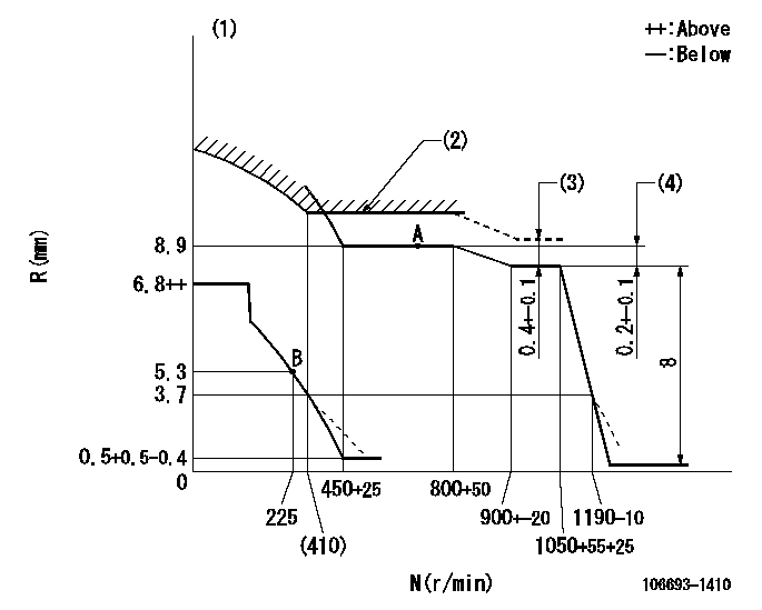
N:Pump speed
R:Rack position (mm)
(1)Damper spring setting: DL
(2)Excess fuel setting for starting: SXL
(3)Tamper proof (shaft setting) (at N = N1).
(4)Rack difference between N = N2 and N = N3
----------
DL=3.7-0.5mm SXL=9.2+0.2mm N1=1000r/min N2=1050r/min N3=650r/min
----------
----------
DL=3.7-0.5mm SXL=9.2+0.2mm N1=1000r/min N2=1050r/min N3=650r/min
----------
Speed control lever angle
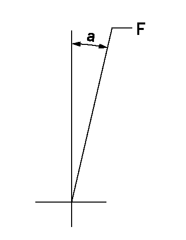
F:Full speed
----------
----------
a=1deg+-5deg
----------
----------
a=1deg+-5deg
0000000901
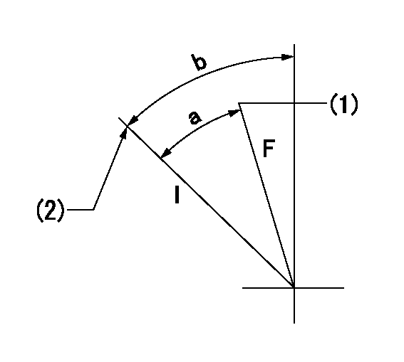
F:Full load
I:Idle
(1)Attach the return spring to the upper hole and adjust.
(2)Stopper bolt setting
----------
----------
a=31deg+-3deg b=30deg+-5deg
----------
----------
a=31deg+-3deg b=30deg+-5deg
Stop lever angle
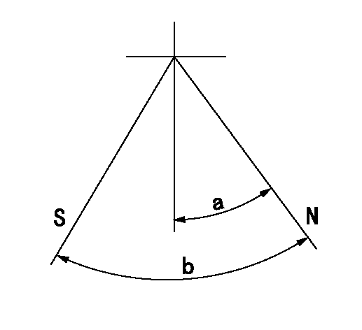
N:Pump normal
S:Stop the pump.
----------
----------
a=32deg+-5deg b=64deg+-5deg
----------
----------
a=32deg+-5deg b=64deg+-5deg
0000001501 TAMPER PROOF
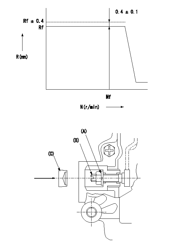
N:Pump speed (r/min)
R:Rack position (mm)
1. After governor adjustment, adjust the shaft as described below and stamp the cap.
(1)Turn the load lever stopper bolt determining the full rack position (R = Rf) 1~2 turns counterclockwise.
(2)Then, increase the full rack position.
(3)Operate the pump at N = Nf and turn the shaft (B) clockwise.
(4)Adjust so that full rack is Rf+0.4.
(5)Tighten nut (A) to the specified torque.
(6)Turn the stopper bolt clockwise the same amount that it was turned counter clockwise in (1).
(7)Then, align with the full rack position (R = Rf) and fix.
(8)Apply thread lock adhesive to the entire circumference of the cap (C) and tap it down to pressfit and seal it..
(9)Check for air tightness.
----------
Rf=8.7mm Nf=1000r/min
----------
----------
Rf=8.7mm Nf=1000r/min
----------
Timing setting

(1)Pump vertical direction
(2)Position of timer's threaded hole at the No. 1 cylinder's beginning of injection
(3)B.T.D.C.: aa
(4)-
----------
aa=21deg
----------
a=(70deg)
----------
aa=21deg
----------
a=(70deg)
Have questions with 106693-1410?
Group cross 106693-1410 ZEXEL
Isuzu
106693-1410
1156017400
INJECTION-PUMP ASSEMBLY
6RB1
6RB1