Rating:
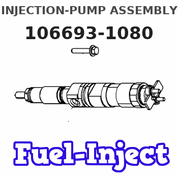
Information injection-pump assembly
BOSCH
9 400 617 902
9400617902
ZEXEL
106693-1080
1066931080
ISUZU
1156014320
1156014320
Service parts 106693-1080 INJECTION-PUMP ASSEMBLY:
1.
_
7.
COUPLING PLATE
8.
_
9.
_
11.
Nozzle and Holder
1-15300-041-2
12.
Open Pre:MPa(Kqf/cm2)
22.1{225}

15.
NOZZLE SET
Include in #1:
106693-1080
as INJECTION-PUMP ASSEMBLY
Cross reference number
BOSCH
9 400 617 902
9400617902
ZEXEL
106693-1080
1066931080
ISUZU
1156014320
1156014320
Zexel num
Bosch num
Firm num
Name
106693-1080
9 400 617 902
1156014320 ISUZU
INJECTION-PUMP ASSEMBLY
6RB1 * K
6RB1 * K
Calibration Data:
Adjustment conditions
Test oil
1404 Test oil ISO4113 or {SAEJ967d}
1404 Test oil ISO4113 or {SAEJ967d}
Test oil temperature
degC
40
40
45
Nozzle and nozzle holder
105780-8140
Bosch type code
EF8511/9A
Nozzle
105780-0000
Bosch type code
DN12SD12T
Nozzle holder
105780-2080
Bosch type code
EF8511/9
Opening pressure
MPa
17.2
Opening pressure
kgf/cm2
175
Injection pipe
Outer diameter - inner diameter - length (mm) mm 8-3-600
Outer diameter - inner diameter - length (mm) mm 8-3-600
Overflow valve
131424-0220
Overflow valve opening pressure
kPa
127
107
147
Overflow valve opening pressure
kgf/cm2
1.3
1.1
1.5
Tester oil delivery pressure
kPa
157
157
157
Tester oil delivery pressure
kgf/cm2
1.6
1.6
1.6
Direction of rotation (viewed from drive side)
Right R
Right R
Injection timing adjustment
Direction of rotation (viewed from drive side)
Right R
Right R
Injection order
1-4-2-6-
3-5
Pre-stroke
mm
3
2.95
3.05
Beginning of injection position
Drive side NO.1
Drive side NO.1
Difference between angles 1
Cal 1-4 deg. 60 59.5 60.5
Cal 1-4 deg. 60 59.5 60.5
Difference between angles 2
Cyl.1-2 deg. 120 119.5 120.5
Cyl.1-2 deg. 120 119.5 120.5
Difference between angles 3
Cal 1-6 deg. 180 179.5 180.5
Cal 1-6 deg. 180 179.5 180.5
Difference between angles 4
Cal 1-3 deg. 240 239.5 240.5
Cal 1-3 deg. 240 239.5 240.5
Difference between angles 5
Cal 1-5 deg. 300 299.5 300.5
Cal 1-5 deg. 300 299.5 300.5
Injection quantity adjustment
Adjusting point
A
Rack position
8.9
Pump speed
r/min
650
650
650
Average injection quantity
mm3/st.
133.9
131.9
135.9
Max. variation between cylinders
%
0
-3
3
Basic
*
Fixing the lever
*
Injection quantity adjustment_02
Adjusting point
B
Rack position
5.3+-0.5
Pump speed
r/min
225
225
225
Average injection quantity
mm3/st.
12.6
9.4
15.8
Max. variation between cylinders
%
0
-13
13
Fixing the rack
*
Injection quantity adjustment_03
Adjusting point
D
Rack position
7.3
Pump speed
r/min
650
650
650
Average injection quantity
mm3/st.
89
85
93
Max. variation between cylinders
%
0
-3
3
Fixing the lever
*
Remarks
At absolute pressure 61.3 kPa {460 mmHg}
At absolute pressure 61.3 kPa {460 mmHg}
Timer adjustment
Pump speed
r/min
500
Advance angle
deg.
0.3
Timer adjustment_02
Pump speed
r/min
700
Advance angle
deg.
1
0.1
1
Timer adjustment_03
Pump speed
r/min
900
Advance angle
deg.
1.2
0.7
1.7
Timer adjustment_04
Pump speed
r/min
1100
Advance angle
deg.
2
1.5
2.5
Remarks
Finish
Finish
Test data Ex:
Governor adjustment
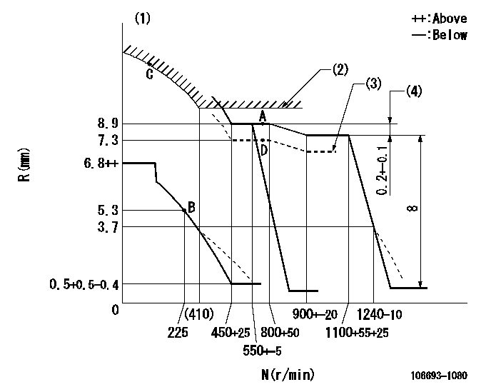
N:Pump speed
R:Rack position (mm)
(1)Beginning of damper spring operation: DL
(2)Excess fuel setting for starting: SXL
(3)Aneroid compensator absolute pressure: P1
(4)Rack difference between N = N1 and N = N2
----------
DL=3.7-0.5mm SXL=9.2+0.2mm P1=61.3+-0.5kPa(460+-5mmHg) N1=1100r/min N2=650r/min
----------
----------
DL=3.7-0.5mm SXL=9.2+0.2mm P1=61.3+-0.5kPa(460+-5mmHg) N1=1100r/min N2=650r/min
----------
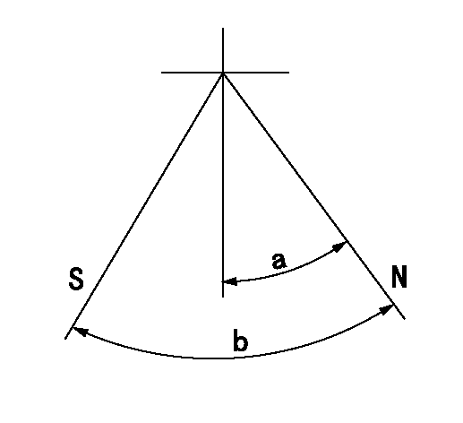
Speed control lever angle
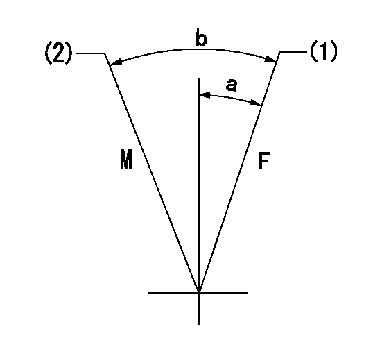
F:Full speed
M:Minimum-maximum speed
(1)Set the pump speed at aa. (At delivery)
(2)Set the speed at bb. Set using two nuts.
----------
aa=1100r/min bb=550r/min
----------
a=1.5deg+-5deg b=8.5deg+-5deg
----------
aa=1100r/min bb=550r/min
----------
a=1.5deg+-5deg b=8.5deg+-5deg
0000000901
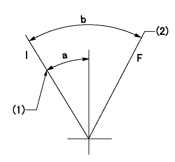
F:Full load
I:Idle
(1)Stopper bolt setting
(2)Attach the return spring to the upper hole and adjust.
----------
----------
a=30deg+-5deg b=31deg+-3deg
----------
----------
a=30deg+-5deg b=31deg+-3deg
Stop lever angle
N:Pump normal
S:Stop the pump.
----------
----------
a=32deg+-5deg b=64deg+-5deg
----------
----------
a=32deg+-5deg b=64deg+-5deg
0000001501 ACS
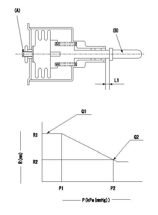
(A) Set screw
(B) Push rod 1
1. Aneroid compensator unit adjustment
(1)Screw in (A) to obtain L1.
2. Adjustment following governor installation
(1)Set the speed of the pump to N1 r/min and fix the control lever at the full set position.
(2)Screw in the aneroid compensator to obtain the performance shown in the graph above.
----------
N1=650r/min L1=(0.6~0.9)mm
----------
R1=8.9mm R2=7.3mm P1=(94.6)kPa((710)mmHg) P2=61.3+-0.7kPa(460+-5mmHg) Q1=133.9+-2cm3/1000st Q2=-
----------
N1=650r/min L1=(0.6~0.9)mm
----------
R1=8.9mm R2=7.3mm P1=(94.6)kPa((710)mmHg) P2=61.3+-0.7kPa(460+-5mmHg) Q1=133.9+-2cm3/1000st Q2=-
Timing setting

(1)Pump vertical direction
(2)Position of timer's threaded hole at No 1 cylinder's beginning of injection
(3)B.T.D.C.: aa
(4)-
----------
aa=21deg
----------
a=(70deg)
----------
aa=21deg
----------
a=(70deg)
Have questions with 106693-1080?
Group cross 106693-1080 ZEXEL
Isuzu
106693-1080
9 400 617 902
1156014320
INJECTION-PUMP ASSEMBLY
6RB1
6RB1