
Rating:
Information injection-pump assembly
BOSCH
9 400 613 393
9400613393
ZEXEL
106682-9881
1066829881
KOMATSU
6212712120
6212712120
Service parts 106682-9881 INJECTION-PUMP ASSEMBLY:
1.
_
5.
AUTOM. ADVANCE MECHANIS
7.
COUPLING PLATE
8.
_
9.
_
11.
Nozzle and Holder
12.
Open Pre:MPa(Kqf/cm2)
24.5{250}
15.
NOZZLE SET
Include in #1:
106682-9881
as INJECTION-PUMP ASSEMBLY
Cross reference number
BOSCH
9 400 613 393
9400613393
ZEXEL
106682-9881
1066829881
KOMATSU
6212712120
6212712120
Zexel num
Bosch num
Firm num
Name
106682-9881
9 400 613 393
6212712120 KOMATSU
INJECTION-PUMP ASSEMBLY
SA6D140 K 14CA INJECTION PUMP ASSY PE6P,6PD PE
SA6D140 K 14CA INJECTION PUMP ASSY PE6P,6PD PE
Calibration Data:
Adjustment conditions
Test oil
1404 Test oil ISO4113 or {SAEJ967d}
1404 Test oil ISO4113 or {SAEJ967d}
Test oil temperature
degC
40
40
45
Nozzle and nozzle holder
105780-8130
Bosch type code
EFEP215A
Nozzle
105780-0050
Bosch type code
DN6TD119NP1T
Nozzle holder
105780-2090
Bosch type code
EFEP215
Opening pressure
MPa
17.2
Opening pressure
kgf/cm2
175
Injection pipe
Outer diameter - inner diameter - length (mm) mm 8-4-1000
Outer diameter - inner diameter - length (mm) mm 8-4-1000
Overflow valve
131425-1620
Overflow valve opening pressure
kPa
255
255
255
Overflow valve opening pressure
kgf/cm2
2.6
2.6
2.6
Tester oil delivery pressure
kPa
157
157
157
Tester oil delivery pressure
kgf/cm2
1.6
1.6
1.6
Direction of rotation (viewed from drive side)
Right R
Right R
Injection timing adjustment
Direction of rotation (viewed from drive side)
Right R
Right R
Injection order
1-5-3-6-
2-4
Pre-stroke
mm
3.85
3.8
3.9
Beginning of injection position
Drive side NO.1
Drive side NO.1
Difference between angles 1
Cal 1-5 deg. 60 59.5 60.5
Cal 1-5 deg. 60 59.5 60.5
Difference between angles 2
Cal 1-3 deg. 120 119.5 120.5
Cal 1-3 deg. 120 119.5 120.5
Difference between angles 3
Cal 1-6 deg. 180 179.5 180.5
Cal 1-6 deg. 180 179.5 180.5
Difference between angles 4
Cyl.1-2 deg. 240 239.5 240.5
Cyl.1-2 deg. 240 239.5 240.5
Difference between angles 5
Cal 1-4 deg. 300 299.5 300.5
Cal 1-4 deg. 300 299.5 300.5
Injection quantity adjustment
Adjusting point
A
Rack position
14.1
Pump speed
r/min
1000
1000
1000
Average injection quantity
mm3/st.
344
341
347
Max. variation between cylinders
%
0
-3
3
Basic
*
Fixing the lever
*
Boost pressure
kPa
101
101
Boost pressure
mmHg
760
760
Injection quantity adjustment_02
Adjusting point
B
Rack position
8+-0.5
Pump speed
r/min
335
335
335
Average injection quantity
mm3/st.
11.5
10
13
Max. variation between cylinders
%
0
-15
15
Fixing the rack
*
Boost pressure
kPa
0
0
0
Boost pressure
mmHg
0
0
0
Injection quantity adjustment_03
Adjusting point
E
Rack position
-
Pump speed
r/min
100
100
100
Average injection quantity
mm3/st.
305
295
315
Fixing the lever
*
Boost pressure
kPa
0
0
0
Boost pressure
mmHg
0
0
0
Rack limit
*
Boost compensator adjustment
Pump speed
r/min
700
700
700
Rack position
12.45
Boost pressure
kPa
14.7
14.7
14.7
Boost pressure
mmHg
110
110
110
Boost compensator adjustment_02
Pump speed
r/min
700
700
700
Rack position
13.45
Boost pressure
kPa
45.3
42.6
48
Boost pressure
mmHg
340
320
360
Boost compensator adjustment_03
Pump speed
r/min
700
700
700
Rack position
14.6
Boost pressure
kPa
84
77.3
90.7
Boost pressure
mmHg
630
580
680
Test data Ex:
Governor adjustment
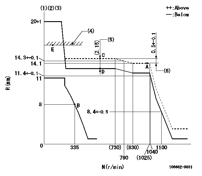
N:Pump speed
R:Rack position (mm)
(1)Target notch: K
(2)Tolerance for racks not indicated: +-0.05mm.
(3)At governor adjustment, set the stop lever at the normal position.
(4)RACK LIMIT
(5)Boost compensator stroke
(6)Rack difference between N = N1 and N = N2
----------
K=24 N1=1000r/min N2=700r/min
----------
----------
K=24 N1=1000r/min N2=700r/min
----------
Speed control lever angle
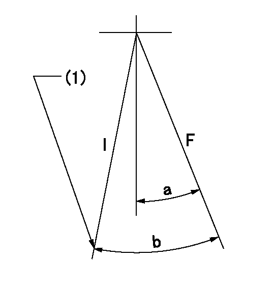
F:Full speed
I:Idle
(1)Stopper bolt setting
----------
----------
a=10deg+-5deg b=22deg+-5deg
----------
----------
a=10deg+-5deg b=22deg+-5deg
Stop lever angle
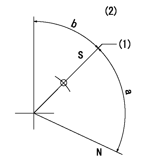
N:Pump normal
S:Stop the pump.
(1)Pump speed aa and rack position bb (to be sealed at delivery)
(2)No return spring
----------
aa=0r/min bb=1-0.5mm
----------
a=(73deg) b=43.5deg+-5deg
----------
aa=0r/min bb=1-0.5mm
----------
a=(73deg) b=43.5deg+-5deg
Timing setting
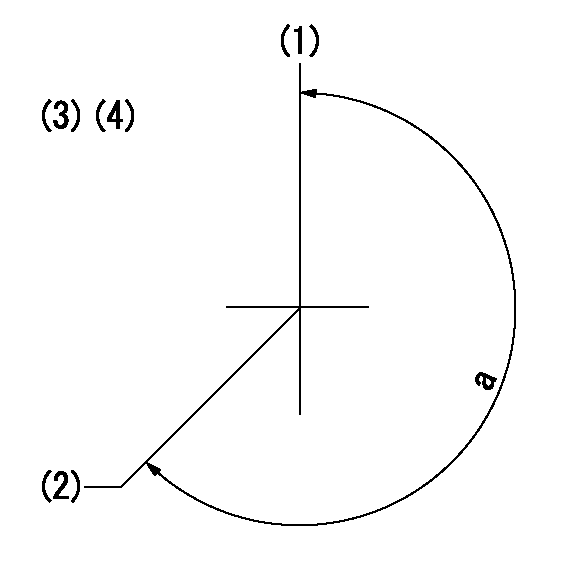
(1)Pump vertical direction
(2)Coupling's key groove position at No 1 cylinder's beginning of injection
(3)-
(4)-
----------
----------
a=(260deg)
----------
----------
a=(260deg)
Have questions with 106682-9881?
Group cross 106682-9881 ZEXEL
Komatsu
Komatsu
Mitsubishi-Heav
Komatsu
Komatsu
Komatsu
Komatsu
Komatsu
106682-9881
9 400 613 393
6212712120
INJECTION-PUMP ASSEMBLY
SA6D140
SA6D140