
Rating:
Information injection-pump assembly
BOSCH
9 400 612 402
9400612402
ZEXEL
106682-9610
1066829610
KOMATSU
6166711531
6166711531
Service parts 106682-9610 INJECTION-PUMP ASSEMBLY:
1.
_
6.
COUPLING PLATE
7.
COUPLING PLATE
8.
_
9.
_
11.
Nozzle and Holder
6162-13-3701
12.
Open Pre:MPa(Kqf/cm2)
26.0{265}
15.
NOZZLE SET
Include in #1:
106682-9610
as INJECTION-PUMP ASSEMBLY
Cross reference number
BOSCH
9 400 612 402
9400612402
ZEXEL
106682-9610
1066829610
KOMATSU
6166711531
6166711531
Zexel num
Bosch num
Firm num
Name
106682-9610
9 400 612 402
6166711531 KOMATSU
INJECTION-PUMP ASSEMBLY
SA12V170 K 14CA INJECTION PUMP ASSY PE6P,6PD PE
SA12V170 K 14CA INJECTION PUMP ASSY PE6P,6PD PE
Calibration Data:
Adjustment conditions
Test oil
1404 Test oil ISO4113 or {SAEJ967d}
1404 Test oil ISO4113 or {SAEJ967d}
Test oil temperature
degC
40
40
45
Nozzle and nozzle holder
105780-8130
Bosch type code
EFEP215A
Nozzle
105780-0050
Bosch type code
DN6TD119NP1T
Nozzle holder
105780-2090
Bosch type code
EFEP215
Opening pressure
MPa
17.2
Opening pressure
kgf/cm2
175
Injection pipe
Outer diameter - inner diameter - length (mm) mm 8-4-1000
Outer diameter - inner diameter - length (mm) mm 8-4-1000
Overflow valve
131425-1620
Overflow valve opening pressure
kPa
255
221
289
Overflow valve opening pressure
kgf/cm2
2.6
2.25
2.95
Tester oil delivery pressure
kPa
157
157
157
Tester oil delivery pressure
kgf/cm2
1.6
1.6
1.6
Direction of rotation (viewed from drive side)
Left L
Left L
Injection timing adjustment
Direction of rotation (viewed from drive side)
Left L
Left L
Injection order
1-5-3-6-
2-4
Pre-stroke
mm
2.8
2.75
2.85
Beginning of injection position
Drive side NO.1
Drive side NO.1
Difference between angles 1
Cal 1-5 deg. 60 59.5 60.5
Cal 1-5 deg. 60 59.5 60.5
Difference between angles 2
Cal 1-3 deg. 120 119.5 120.5
Cal 1-3 deg. 120 119.5 120.5
Difference between angles 3
Cal 1-6 deg. 180 179.5 180.5
Cal 1-6 deg. 180 179.5 180.5
Difference between angles 4
Cyl.1-2 deg. 240 239.5 240.5
Cyl.1-2 deg. 240 239.5 240.5
Difference between angles 5
Cal 1-4 deg. 300 299.5 300.5
Cal 1-4 deg. 300 299.5 300.5
Injection quantity adjustment
Adjusting point
A
Rack position
15.7
Pump speed
r/min
900
900
900
Average injection quantity
mm3/st.
395
390
400
Max. variation between cylinders
%
0
-3
3
Basic
*
Fixing the lever
*
Boost pressure
kPa
53.3
53.3
Boost pressure
mmHg
400
400
Remarks
Standard point A's rack position same as row R
Standard point A's rack position same as row R
Injection quantity adjustment_02
Adjusting point
C
Rack position
7.1+-0.5
Pump speed
r/min
330
330
330
Average injection quantity
mm3/st.
31
26
36
Max. variation between cylinders
%
0
-15
15
Fixing the rack
*
Boost pressure
kPa
0
0
0
Boost pressure
mmHg
0
0
0
Boost compensator adjustment
Pump speed
r/min
650
650
650
Rack position
R1-2.2
Boost pressure
kPa
13.3
10.6
16
Boost pressure
mmHg
100
80
120
Boost compensator adjustment_02
Pump speed
r/min
650
650
650
Rack position
R1(17.1)
Boost pressure
kPa
40
33.3
46.7
Boost pressure
mmHg
300
250
350
Test data Ex:
Governor adjustment
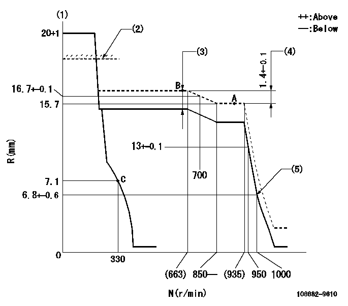
N:Pump speed
R:Rack position (mm)
(1)Target notch: K
(2)RACK LIMIT for 106684-4170
(3)Boost compensator stroke: BCL
(4)Rack difference between N = N1 and N = N2
(5)Idle sub spring setting: L1.
----------
K=20 BCL=2.2+-0.1mm N1=900r/min N2=650r/min L1=6.8-0.5mm
----------
----------
K=20 BCL=2.2+-0.1mm N1=900r/min N2=650r/min L1=6.8-0.5mm
----------
Speed control lever angle
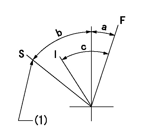
F:Full speed
I:Idle
S:Stop
(1)Stopper bolt setting
----------
----------
a=(19deg)+-5deg b=33deg+-3deg c=(31deg)+-5deg
----------
----------
a=(19deg)+-5deg b=33deg+-3deg c=(31deg)+-5deg
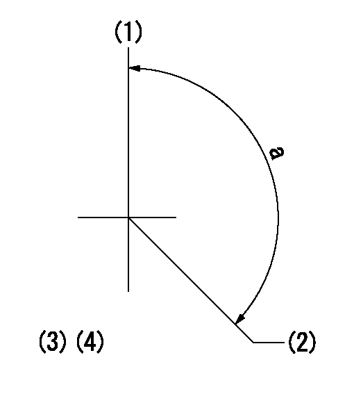
Stop lever angle
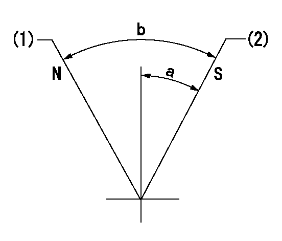
N:Pump normal
S:Stop the pump.
(1)Normal
(2)Pump speed aa and rack position bb (to be sealed at delivery)
----------
aa=0r/min bb=1-0.5mm
----------
a=29deg+-5deg b=(73deg)
----------
aa=0r/min bb=1-0.5mm
----------
a=29deg+-5deg b=(73deg)
0000001501 LEVER
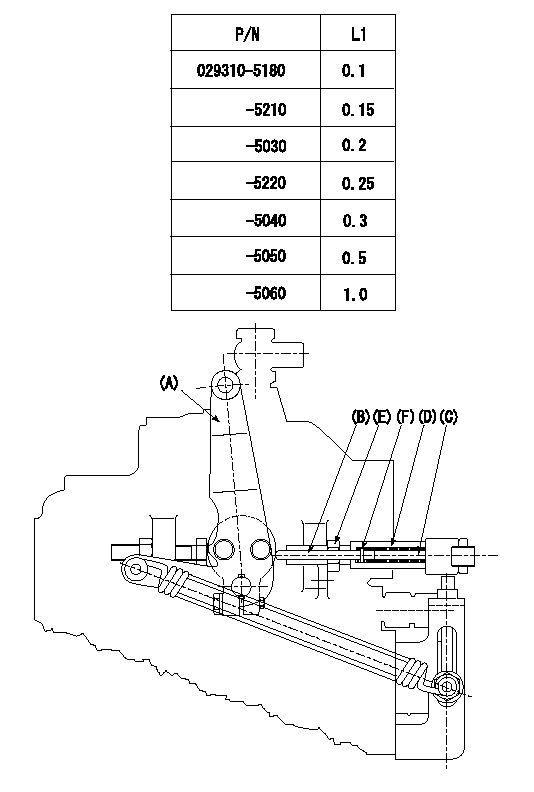
Speed lever adjustment
1. (1) For idling hold the speed lever (a) against the push rod (B).
(2)At this time, confirm that the spring (C) is not bent by the operating torque of the speed lever.
2. (1) To stop, bend the spring (C) using the speed lever.
(2)Position the rack at L2. (Adjustment is performed using the shim (F).)
(3)Set and fix using lock nut (E) so that it contacts the guide screw (D).
3. Confirm that the speed lever returns to the idling position when pulled in the stop direction and then released.
----------
L2=0.2~2mm
----------
----------
L2=0.2~2mm
----------
Timing setting
(1)Pump vertical direction
(2)Position of spline gear's aligning mark at No 1 cylinder's beginning of injection (key position)
(3)B.T.D.C.: aa
(4)-
----------
aa=34deg
----------
a=(130deg)
----------
aa=34deg
----------
a=(130deg)
Have questions with 106682-9610?
Group cross 106682-9610 ZEXEL
Komatsu
106682-9610
9 400 612 402
6166711531
INJECTION-PUMP ASSEMBLY
SA12V170
SA12V170