
Rating:
Information injection-pump assembly
ZEXEL
106682-4891
1066824891
KOMATSU
6162731942
6162731942
Service parts 106682-4891 INJECTION-PUMP ASSEMBLY:
1.
_
5.
AUTOM. ADVANCE MECHANIS
7.
COUPLING PLATE
8.
_
9.
_
11.
Nozzle and Holder
6162-13-7302
12.
Open Pre:MPa(Kqf/cm2)
26.0{265}
15.
NOZZLE SET
Include in #1:
106682-4891
as INJECTION-PUMP ASSEMBLY
Cross reference number
ZEXEL
106682-4891
1066824891
KOMATSU
6162731942
6162731942
Zexel num
Bosch num
Firm num
Name
Calibration Data:
Adjustment conditions
Test oil
1404 Test oil ISO4113 or {SAEJ967d}
1404 Test oil ISO4113 or {SAEJ967d}
Test oil temperature
degC
40
40
45
Nozzle and nozzle holder
105780-8130
Bosch type code
EFEP215A
Nozzle
105780-0050
Bosch type code
DN6TD119NP1T
Nozzle holder
105780-2090
Bosch type code
EFEP215
Opening pressure
MPa
17.2
Opening pressure
kgf/cm2
175
Injection pipe
Outer diameter - inner diameter - length (mm) mm 8-4-1000
Outer diameter - inner diameter - length (mm) mm 8-4-1000
Overflow valve
131425-1620
Overflow valve opening pressure
kPa
255
221
289
Overflow valve opening pressure
kgf/cm2
2.6
2.25
2.95
Tester oil delivery pressure
kPa
157
157
157
Tester oil delivery pressure
kgf/cm2
1.6
1.6
1.6
Direction of rotation (viewed from drive side)
Left L
Left L
Injection timing adjustment
Direction of rotation (viewed from drive side)
Left L
Left L
Injection order
1-5-3-6-
2-4
Pre-stroke
mm
3
2.95
3.05
Beginning of injection position
Drive side NO.1
Drive side NO.1
Difference between angles 1
Cal 1-5 deg. 60 59.5 60.5
Cal 1-5 deg. 60 59.5 60.5
Difference between angles 2
Cal 1-3 deg. 120 119.5 120.5
Cal 1-3 deg. 120 119.5 120.5
Difference between angles 3
Cal 1-6 deg. 180 179.5 180.5
Cal 1-6 deg. 180 179.5 180.5
Difference between angles 4
Cyl.1-2 deg. 240 239.5 240.5
Cyl.1-2 deg. 240 239.5 240.5
Difference between angles 5
Cal 1-4 deg. 300 299.5 300.5
Cal 1-4 deg. 300 299.5 300.5
Injection quantity adjustment
Adjusting point
A
Rack position
17.4
Pump speed
r/min
750
750
750
Average injection quantity
mm3/st.
446
441
451
Max. variation between cylinders
%
0
-3
3
Basic
*
Fixing the rack
*
Injection quantity adjustment_02
Adjusting point
B
Rack position
9.3+-0.5
Pump speed
r/min
400
400
400
Average injection quantity
mm3/st.
37
32
42
Max. variation between cylinders
%
0
-15
15
Fixing the rack
*
Injection quantity adjustment_03
Adjusting point
E
Rack position
20+1
Pump speed
r/min
100
100
100
Average injection quantity
mm3/st.
500
500
Fixing the lever
*
Test data Ex:
Governor adjustment
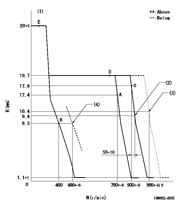
N:Pump speed
R:Rack position (mm)
(1)Target notch: K
(2)Idle sub spring setting: L1.
(3)Set at delivery
(4)Dead point position: set at speed N = N1, rack position R = R1
----------
K=10 L1=9.4-0.5mm N1=460+-5r/min R1=9.3mm
----------
----------
K=10 L1=9.4-0.5mm N1=460+-5r/min R1=9.3mm
----------
Speed control lever angle
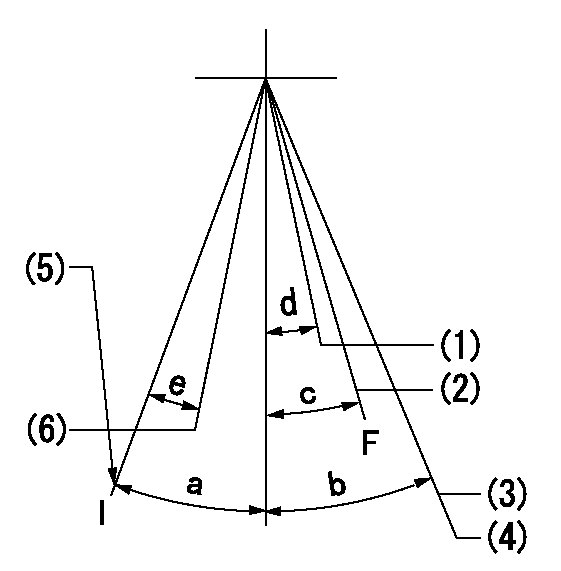
F:Full speed
I:Idle
(1)Set the pump speed at aa
(2)Set the pump speed at bb.
(3)Set the speed at cc (at delivery)
(4)Stopper bolt setting
(5)Stopper bolt setting
(6)Dead point position: Set at speed = dd, rack position = ee
----------
aa=750r/min bb=900r/min cc=965r/min dd=460+-5r/min ee=9.3mm
----------
a=18deg+-5deg b=(14deg) c=12deg+-5deg d=3deg+-5deg e=(2.5deg)
----------
aa=750r/min bb=900r/min cc=965r/min dd=460+-5r/min ee=9.3mm
----------
a=18deg+-5deg b=(14deg) c=12deg+-5deg d=3deg+-5deg e=(2.5deg)
Stop lever angle
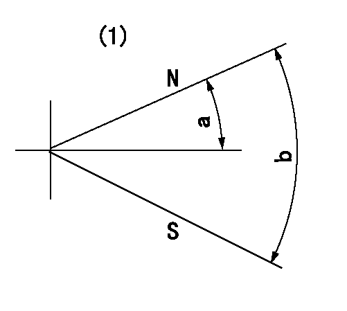
N:Pump normal
S:Stop the pump.
(1)Confirm non-injection at speed = aa.
----------
aa=200r/min
----------
a=26.5deg+-5deg b=53deg+-5deg
----------
aa=200r/min
----------
a=26.5deg+-5deg b=53deg+-5deg
0000001501 LEVER
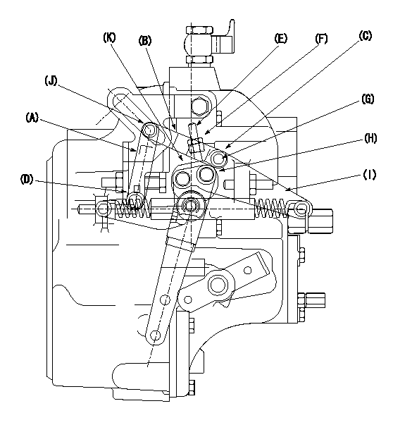
1. (1) Remove the link (A) (B) from (C) and (D).
(2)In this condition, perform normal governor adjustment.
2. (1) Mount the link.
(2)Adjust the umbrella lever.
(3)Adjust the dead point.
Loosen the screw E.
Measure the lever angle when the pump speed is N and the rack position is R.
Temporarily fix the lever with the idle stopper bolt at that angle.
Set the lever (I) with bolts (G) and (H) so that a dead point is obtained.
Check play at the sliding part (J).
Loosen the idle stopper bolt.
Slide the lever.
Re-set the idle stopper bolt at the position of the dead point at that time.
At this time, confirm N, R.
Set so that screw E contacts the lever K.
Fix with the lock nut (F).
3.(1) Set the idle setting.
----------
N=460r/min R=9.3mm
----------
----------
N=460r/min R=9.3mm
----------
Timing setting
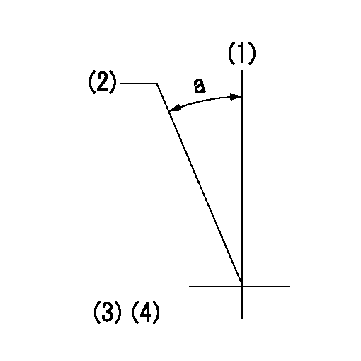
(1)Pump vertical direction
(2)Coupling's key groove position at No 1 cylinder's beginning of injection
(3)-
(4)-
----------
----------
a=(30deg)
----------
----------
a=(30deg)