
Rating:
Information injection-pump assembly
BOSCH
F 01G 09U 0JC
f01g09u0jc
ZEXEL
106682-1121
1066821121
ISUZU
1156035141
1156035141
Service parts 106682-1121 INJECTION-PUMP ASSEMBLY:
1.
_
5.
AUTOM. ADVANCE MECHANIS
7.
COUPLING PLATE
8.
_
9.
_
11.
Nozzle and Holder
12.
Open Pre:MPa(Kqf/cm2)
22.1(225)
15.
NOZZLE SET
Include in #1:
106682-1121
as INJECTION-PUMP ASSEMBLY
Cross reference number
BOSCH
F 01G 09U 0JC
f01g09u0jc
ZEXEL
106682-1121
1066821121
ISUZU
1156035141
1156035141
Zexel num
Bosch num
Firm num
Name
Calibration Data:
Adjustment conditions
Test oil
1404 Test oil ISO4113 or {SAEJ967d}
1404 Test oil ISO4113 or {SAEJ967d}
Test oil temperature
degC
40
40
45
Nozzle and nozzle holder
105780-8130
Bosch type code
EFEP215A
Nozzle
105780-0050
Bosch type code
DN6TD119NP1T
Nozzle holder
105780-2090
Bosch type code
EFEP215
Opening pressure
MPa
17.2
Opening pressure
kgf/cm2
175
Injection pipe
Outer diameter - inner diameter - length (mm) mm 8-4-1000
Outer diameter - inner diameter - length (mm) mm 8-4-1000
Overflow valve
134424-4320
Overflow valve opening pressure
kPa
255
221
289
Overflow valve opening pressure
kgf/cm2
2.6
2.25
2.95
Tester oil delivery pressure
kPa
255
255
255
Tester oil delivery pressure
kgf/cm2
2.6
2.6
2.6
Direction of rotation (viewed from drive side)
Right R
Right R
Injection timing adjustment
Direction of rotation (viewed from drive side)
Right R
Right R
Injection order
1-5-3-6-
2-4
Pre-stroke
mm
2.8
2.75
2.85
Beginning of injection position
Drive side NO.1
Drive side NO.1
Difference between angles 1
Cal 1-5 deg. 60 59.5 60.5
Cal 1-5 deg. 60 59.5 60.5
Difference between angles 2
Cal 1-3 deg. 120 119.5 120.5
Cal 1-3 deg. 120 119.5 120.5
Difference between angles 3
Cal 1-6 deg. 180 179.5 180.5
Cal 1-6 deg. 180 179.5 180.5
Difference between angles 4
Cyl.1-2 deg. 240 239.5 240.5
Cyl.1-2 deg. 240 239.5 240.5
Difference between angles 5
Cal 1-4 deg. 300 299.5 300.5
Cal 1-4 deg. 300 299.5 300.5
Injection quantity adjustment
Adjusting point
A
Rack position
11.3
Pump speed
r/min
1115
1115
1115
Average injection quantity
mm3/st.
417
413
421
Max. variation between cylinders
%
0
-3
3
Basic
*
Fixing the lever
*
Boost pressure
kPa
169
169
Boost pressure
mmHg
1270
1270
Injection quantity adjustment_02
Adjusting point
B
Rack position
4.4+-0.5
Pump speed
r/min
290
290
290
Average injection quantity
mm3/st.
18
14.8
21.2
Max. variation between cylinders
%
0
-15
15
Fixing the rack
*
Boost pressure
kPa
0
0
0
Boost pressure
mmHg
0
0
0
Boost compensator adjustment
Pump speed
r/min
550
550
550
Rack position
R1-4
Boost pressure
kPa
70
66
74
Boost pressure
mmHg
525
495
555
Boost compensator adjustment_02
Pump speed
r/min
550
550
550
Rack position
R1(11.3)
Boost pressure
kPa
156
149.3
162.7
Boost pressure
mmHg
1170
1120
1220
Test data Ex:
Governor adjustment
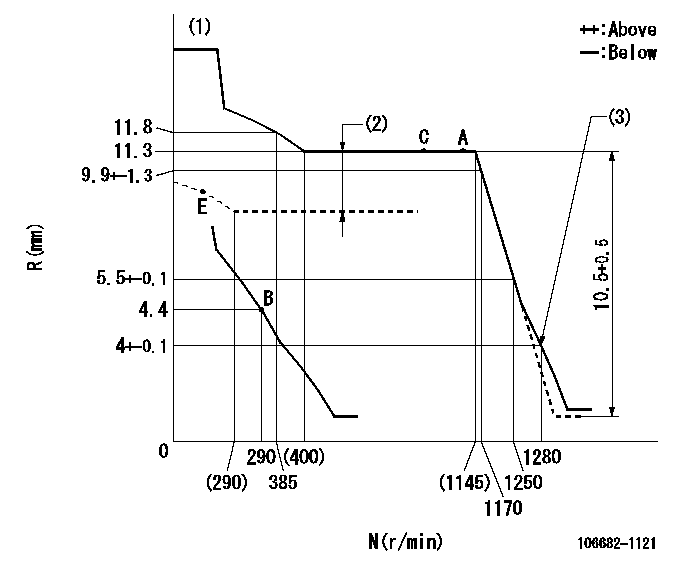
N:Pump speed
R:Rack position (mm)
(1)Tolerance for racks not indicated: +-0.05mm.
(2)Boost compensator stroke: BCL
(3)Set idle sub-spring
----------
BCL=4+-0.1mm
----------
----------
BCL=4+-0.1mm
----------
Speed control lever angle
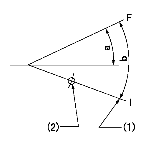
F:Full speed
I:Idle
(1)Stopper bolt setting
(2)Use the hole at R = aa
----------
aa=135mm
----------
a=(4deg)+-5deg b=(14deg)+-5deg
----------
aa=135mm
----------
a=(4deg)+-5deg b=(14deg)+-5deg
0000000901
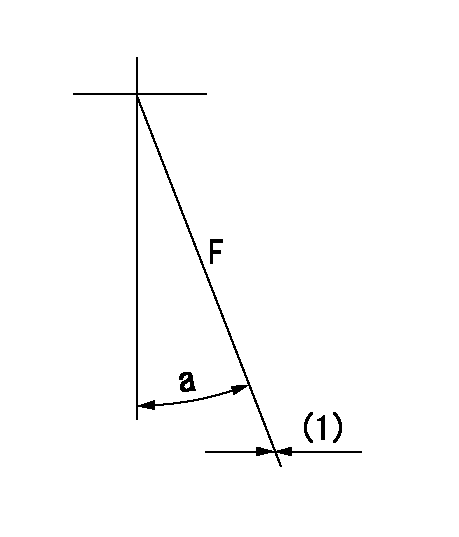
F:Full load
(1)Fix using the stopper bolt.
----------
----------
a=15deg+-5deg
----------
----------
a=15deg+-5deg
Stop lever angle
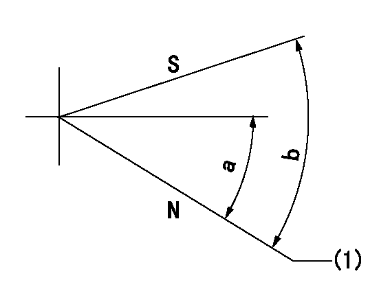
N:Pump normal
S:Stop the pump.
(1)Normal
----------
----------
a=27deg+-5deg b=71deg+-5deg
----------
----------
a=27deg+-5deg b=71deg+-5deg
0000001501 TAMPER PROOF
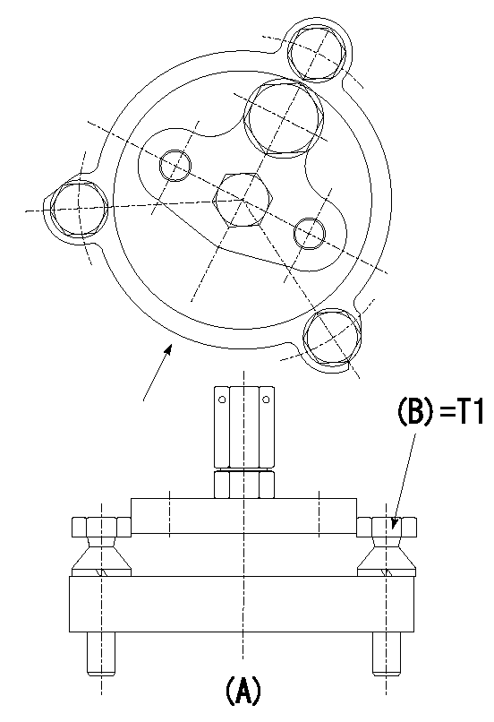
Tamperproofing-equipped boost compensator cover installation procedure
(A): figure shown by arrow
(1)Before adjusting the governor and the boost compensator, temporarily tighten the screw to the specified torque. (Do not damage the thread.)
(Tightening torque T = T1 maximum)
----------
T1=2.5N-m(0.25kgf-m)
----------
----------
T1=2.5N-m(0.25kgf-m)
----------
Timing setting
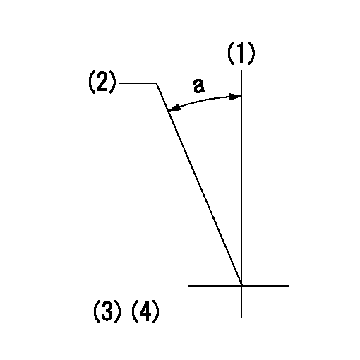
(1)Pump vertical direction
(2)Position of coupling's threaded hole at No 1 cylinder's beginning of injection
(3)B.T.D.C.: aa
(4)-
----------
aa=15deg
----------
a=(30deg)
----------
aa=15deg
----------
a=(30deg)