
Rating:
Information injection-pump assembly
BOSCH
9 400 612 048
9400612048
ZEXEL
106681-4400
1066814400
MITSUBISHI-HEAV
34A6550270
34a6550270
Service parts 106681-4400 INJECTION-PUMP ASSEMBLY:
1.
_
7.
COUPLING PLATE
8.
_
9.
_
11.
Nozzle and Holder
35A61-00010
12.
Open Pre:MPa(Kqf/cm2)
21.6{220}
15.
NOZZLE SET
Include in #1:
106681-4400
as INJECTION-PUMP ASSEMBLY
Cross reference number
BOSCH
9 400 612 048
9400612048
ZEXEL
106681-4400
1066814400
MITSUBISHI-HEAV
34A6550270
34a6550270
Zexel num
Bosch num
Firm num
Name
9 400 612 048
34A6550270 MITSUBISHI-HEAV
INJECTION-PUMP ASSEMBLY
S6B3-TA * K
S6B3-TA * K
Calibration Data:
Adjustment conditions
Test oil
1404 Test oil ISO4113 or {SAEJ967d}
1404 Test oil ISO4113 or {SAEJ967d}
Test oil temperature
degC
40
40
45
Nozzle and nozzle holder
105780-8130
Bosch type code
EFEP215A
Nozzle
105780-0050
Bosch type code
DN6TD119NP1T
Nozzle holder
105780-2090
Bosch type code
EFEP215
Opening pressure
MPa
17.2
Opening pressure
kgf/cm2
175
Injection pipe
Outer diameter - inner diameter - length (mm) mm 8-4-1000
Outer diameter - inner diameter - length (mm) mm 8-4-1000
Overflow valve
131424-3420
Overflow valve opening pressure
kPa
255
221
289
Overflow valve opening pressure
kgf/cm2
2.6
2.25
2.95
Tester oil delivery pressure
kPa
157
157
157
Tester oil delivery pressure
kgf/cm2
1.6
1.6
1.6
Direction of rotation (viewed from drive side)
Left L
Left L
Injection timing adjustment
Direction of rotation (viewed from drive side)
Left L
Left L
Injection order
1-5-3-6-
2-4
Pre-stroke
mm
2.8
2.75
2.85
Beginning of injection position
Governor side NO.1
Governor side NO.1
Difference between angles 1
Cal 1-5 deg. 60 59.5 60.5
Cal 1-5 deg. 60 59.5 60.5
Difference between angles 2
Cal 1-3 deg. 120 119.5 120.5
Cal 1-3 deg. 120 119.5 120.5
Difference between angles 3
Cal 1-6 deg. 180 179.5 180.5
Cal 1-6 deg. 180 179.5 180.5
Difference between angles 4
Cyl.1-2 deg. 240 239.5 240.5
Cyl.1-2 deg. 240 239.5 240.5
Difference between angles 5
Cal 1-4 deg. 300 299.5 300.5
Cal 1-4 deg. 300 299.5 300.5
Injection quantity adjustment
Adjusting point
A
Rack position
11.2
Pump speed
r/min
750
750
750
Average injection quantity
mm3/st.
303
294
312
Max. variation between cylinders
%
0
-3
3
Basic
*
Fixing the lever
*
Boost pressure
kPa
117
117
Boost pressure
mmHg
875
875
Remarks
Injection at all cylinders.
Injection at all cylinders.
Injection quantity adjustment_02
Adjusting point
C
Rack position
5.6+-0.5
Pump speed
r/min
350
350
350
Average injection quantity
mm3/st.
26
23
29
Max. variation between cylinders
%
0
-10
10
Fixing the rack
*
Boost pressure
kPa
0
0
0
Boost pressure
mmHg
0
0
0
Remarks
Injection only at cylinders 1, 3, 4 and 6.
Injection only at cylinders 1, 3, 4 and 6.
Injection quantity adjustment_03
Adjusting point
E
Rack position
-
Pump speed
r/min
100
100
100
Average injection quantity
mm3/st.
260
260
280
Fixing the lever
*
Boost pressure
kPa
0
0
0
Boost pressure
mmHg
0
0
0
Rack limit
*
Boost compensator adjustment
Pump speed
r/min
500
500
500
Rack position
R1-2.5
Boost pressure
kPa
58.7
52
65.4
Boost pressure
mmHg
440
390
490
Boost compensator adjustment_02
Pump speed
r/min
500
500
500
Rack position
R1(11.2)
Boost pressure
kPa
107
104.3
109.7
Boost pressure
mmHg
805
785
825
Timer adjustment
Pump speed
r/min
450--
Advance angle
deg.
0
0
0
Remarks
Start
Start
Timer adjustment_02
Pump speed
r/min
400
Advance angle
deg.
0.5
Timer adjustment_03
Pump speed
r/min
700
Advance angle
deg.
4
3.5
4.5
Remarks
Finish
Finish
Test data Ex:
Governor adjustment
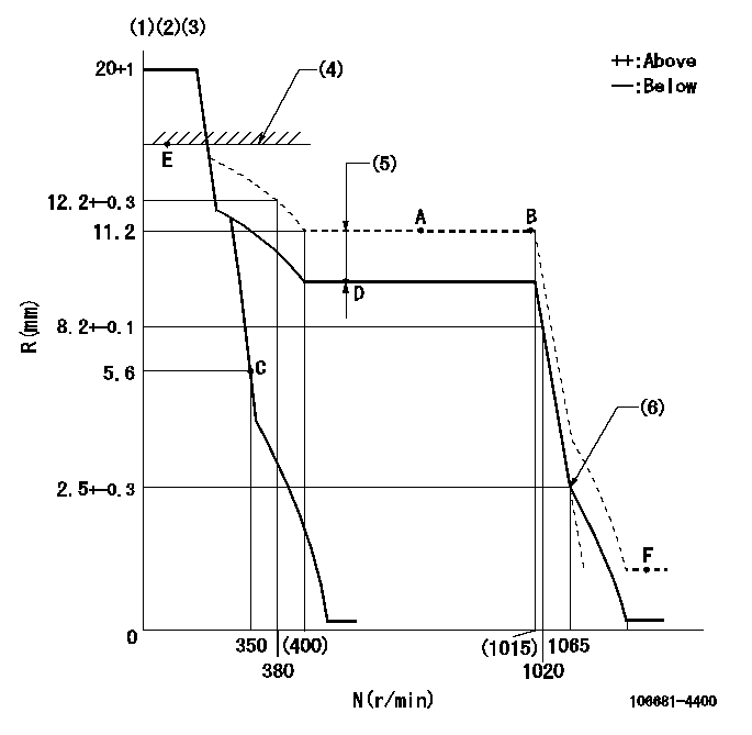
N:Pump speed
R:Rack position (mm)
(1)Target notch: K
(2)Tolerance for racks not indicated: +-0.05mm.
(3)The torque control spring does not operate.
(4)RACK LIMIT
(5)Boost compensator stroke: BCL
(6)Idle sub spring setting: L1.
----------
K=15 BCL=2.5+-0.1mm L1=2.5-0.5mm
----------
----------
K=15 BCL=2.5+-0.1mm L1=2.5-0.5mm
----------
Speed control lever angle
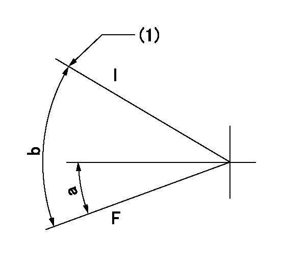
F:Full speed
I:Idle
(1)Stopper bolt setting
----------
----------
a=0deg+-5deg b=24deg+-5deg
----------
----------
a=0deg+-5deg b=24deg+-5deg
Stop lever angle
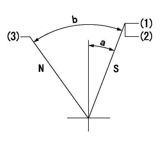
N:Pump normal
S:Stop the pump.
(1)Pump speed aa, rack position bb
(2)Seal at delivery.
(3)Normal
----------
aa=0r/min bb=3-0.5mm
----------
a=27deg+-5deg b=62.5deg+-5deg
----------
aa=0r/min bb=3-0.5mm
----------
a=27deg+-5deg b=62.5deg+-5deg
Timing setting
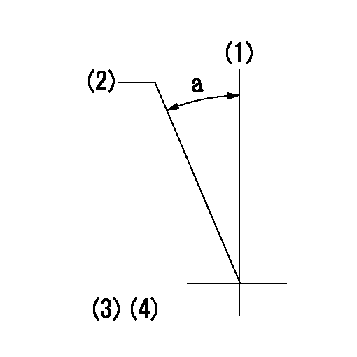
(1)Pump vertical direction
(2)Coupling's key groove position at No 1 cylinder's beginning of injection
(3)-
(4)-
----------
----------
a=(20deg)
----------
----------
a=(20deg)