Rating:
Information injection-pump assembly
BOSCH
9 400 613 271
9400613271
ZEXEL
106676-2560
1066762560
MITSUBISHI
ME350752
me350752
Service parts 106676-2560 INJECTION-PUMP ASSEMBLY:
1.
_

7.
COUPLING PLATE
8.
_
9.
_
11.
Nozzle and Holder
ME152406
12.
Open Pre:MPa(Kqf/cm2)
17.7{180}/24.5{250}
14.
NOZZLE
Include in #1:
106676-2560
as INJECTION-PUMP ASSEMBLY
Cross reference number
BOSCH
9 400 613 271
9400613271
ZEXEL
106676-2560
1066762560
MITSUBISHI
ME350752
me350752
Zexel num
Bosch num
Firm num
Name
106676-2560
9 400 613 271
ME350752 MITSUBISHI
INJECTION-PUMP ASSEMBLY
6D24 K 14CA INJECTION PUMP ASSY PE6P,6PD PE
6D24 K 14CA INJECTION PUMP ASSY PE6P,6PD PE
Calibration Data:
Adjustment conditions
Test oil
1404 Test oil ISO4113 or {SAEJ967d}
1404 Test oil ISO4113 or {SAEJ967d}
Test oil temperature
degC
40
40
45
Nozzle and nozzle holder
105780-8250
Bosch type code
1 688 901 101
Nozzle
105780-0120
Bosch type code
1 688 901 990
Nozzle holder
105780-2190
Opening pressure
MPa
20.7
Opening pressure
kgf/cm2
211
Injection pipe
Outer diameter - inner diameter - length (mm) mm 8-3-600
Outer diameter - inner diameter - length (mm) mm 8-3-600
Overflow valve
131425-0220
Overflow valve opening pressure
kPa
157
157
157
Overflow valve opening pressure
kgf/cm2
1.6
1.6
1.6
Tester oil delivery pressure
kPa
255
255
255
Tester oil delivery pressure
kgf/cm2
2.6
2.6
2.6
Direction of rotation (viewed from drive side)
Right R
Right R
Injection timing adjustment
Direction of rotation (viewed from drive side)
Right R
Right R
Injection order
1-5-3-6-
2-4
Pre-stroke
mm
3.9
3.85
3.95
Beginning of injection position
Governor side NO.1
Governor side NO.1
Difference between angles 1
Cal 1-5 deg. 60 59.5 60.5
Cal 1-5 deg. 60 59.5 60.5
Difference between angles 2
Cal 1-3 deg. 120 119.5 120.5
Cal 1-3 deg. 120 119.5 120.5
Difference between angles 3
Cal 1-6 deg. 180 179.5 180.5
Cal 1-6 deg. 180 179.5 180.5
Difference between angles 4
Cyl.1-2 deg. 240 239.5 240.5
Cyl.1-2 deg. 240 239.5 240.5
Difference between angles 5
Cal 1-4 deg. 300 299.5 300.5
Cal 1-4 deg. 300 299.5 300.5
Injection quantity adjustment
Adjusting point
-
Rack position
11.9
Pump speed
r/min
700
700
700
Each cylinder's injection qty
mm3/st.
118.5
115.5
121.5
Basic
*
Fixing the rack
*
Standard for adjustment of the maximum variation between cylinders
*
Injection quantity adjustment_02
Adjusting point
Z
Rack position
8.5+-0.5
Pump speed
r/min
410
410
410
Each cylinder's injection qty
mm3/st.
15.8
13.4
18.2
Fixing the rack
*
Standard for adjustment of the maximum variation between cylinders
*
Injection quantity adjustment_03
Adjusting point
A
Rack position
R1(11.9)
Pump speed
r/min
700
700
700
Average injection quantity
mm3/st.
118.5
117.5
119.5
Basic
*
Fixing the lever
*
Injection quantity adjustment_04
Adjusting point
B
Rack position
R1+0.9
Pump speed
r/min
1100
1100
1100
Average injection quantity
mm3/st.
117
113
121
Fixing the lever
*
Injection quantity adjustment_05
Adjusting point
C
Rack position
(R1+0.7)
Pump speed
r/min
900
900
900
Average injection quantity
mm3/st.
124
120
128
Fixing the lever
*
Injection quantity adjustment_06
Adjusting point
D
Rack position
R1-0.65
Pump speed
r/min
500
500
500
Average injection quantity
mm3/st.
112.5
106.5
118.5
Fixing the lever
*
Timer adjustment
Pump speed
r/min
800--
Advance angle
deg.
0
0
0
Remarks
Start
Start
Timer adjustment_02
Pump speed
r/min
750
Advance angle
deg.
0.5
Timer adjustment_03
Pump speed
r/min
1100
Advance angle
deg.
2
1.5
2.5
Remarks
Finish
Finish
Test data Ex:
Governor adjustment
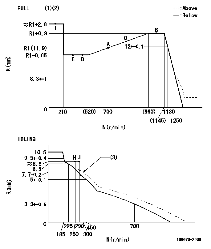
N:Pump speed
R:Rack position (mm)
(1)Torque cam stamping: T1
(2)Tolerance for racks not indicated: +-0.05mm.
(3)Damper spring setting
----------
T1=AE41
----------
----------
T1=AE41
----------
Speed control lever angle
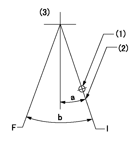
F:Full speed
I:Idle
(1)Use the hole at R = aa
(2)Stopper bolt setting
(3)Viewed from feed pump side.
----------
aa=37.5mm
----------
a=1deg+-5deg b=(36.5deg)+-3deg
----------
aa=37.5mm
----------
a=1deg+-5deg b=(36.5deg)+-3deg
Stop lever angle
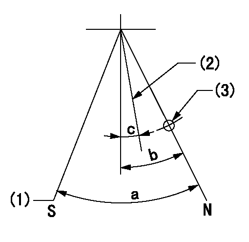
N:Pump normal
S:Stop the pump.
(1)At pump speed aa and rack position bb, set the stopper bolt. (Confirm non-injection.)
(2)Normal engine position (equivalent to R = cc).
(3)Use the hole above R = dd
----------
aa=1100r/min bb=3.5+-0.3mm cc=18mm dd=54mm
----------
a=41deg+-5deg b=29.5deg+-5deg c=(20.5deg)+-5deg
----------
aa=1100r/min bb=3.5+-0.3mm cc=18mm dd=54mm
----------
a=41deg+-5deg b=29.5deg+-5deg c=(20.5deg)+-5deg
Timing setting

(1)Pump vertical direction
(2)Coupling's key groove position at No 1 cylinder's beginning of injection
(3)B.T.D.C.: aa
(4)-
----------
aa=12deg
----------
a=(8deg)
----------
aa=12deg
----------
a=(8deg)
Have questions with 106676-2560?
Group cross 106676-2560 ZEXEL
Mitsubishi
Mitsubishi
106676-2560
9 400 613 271
ME350752
INJECTION-PUMP ASSEMBLY
6D24
6D24