Rating:
Information injection-pump assembly
BOSCH
9 400 617 441
9400617441
ZEXEL
106676-2342
1066762342
MITSUBISHI
ME158829
me158829
Service parts 106676-2342 INJECTION-PUMP ASSEMBLY:
1.
_
7.
COUPLING PLATE
8.
_
9.
_
11.
Nozzle and Holder
ME158263
12.
Open Pre:MPa(Kqf/cm2)
17.7{180}/21.6{220}
14.
NOZZLE
Include in #1:
106676-2342
as INJECTION-PUMP ASSEMBLY
Cross reference number
BOSCH
9 400 617 441
9400617441
ZEXEL
106676-2342
1066762342
MITSUBISHI
ME158829
me158829
Zexel num
Bosch num
Firm num
Name
9 400 617 441
ME158829 MITSUBISHI
INJECTION-PUMP ASSEMBLY
6D24-T * K 14CA INJECTION PUMP ASSY PE6P,6PD PE
6D24-T * K 14CA INJECTION PUMP ASSY PE6P,6PD PE
Calibration Data:
Adjustment conditions
Test oil
1404 Test oil ISO4113 or {SAEJ967d}
1404 Test oil ISO4113 or {SAEJ967d}
Test oil temperature
degC
40
40
45
Nozzle and nozzle holder
105780-8140
Bosch type code
EF8511/9A
Nozzle
105780-0000
Bosch type code
DN12SD12T
Nozzle holder
105780-2080
Bosch type code
EF8511/9
Opening pressure
MPa
17.2
Opening pressure
kgf/cm2
175
Injection pipe
Outer diameter - inner diameter - length (mm) mm 8-3-600
Outer diameter - inner diameter - length (mm) mm 8-3-600
Overflow valve
131424-4620
Overflow valve opening pressure
kPa
255
221
289
Overflow valve opening pressure
kgf/cm2
2.6
2.25
2.95
Tester oil delivery pressure
kPa
157
157
157
Tester oil delivery pressure
kgf/cm2
1.6
1.6
1.6
Direction of rotation (viewed from drive side)
Right R
Right R
Injection timing adjustment
Direction of rotation (viewed from drive side)
Right R
Right R
Injection order
1-5-3-6-
2-4
Pre-stroke
mm
4.8
4.75
4.85
Beginning of injection position
Governor side NO.1
Governor side NO.1
Difference between angles 1
Cal 1-5 deg. 60 59.5 60.5
Cal 1-5 deg. 60 59.5 60.5
Difference between angles 2
Cal 1-3 deg. 120 119.5 120.5
Cal 1-3 deg. 120 119.5 120.5
Difference between angles 3
Cal 1-6 deg. 180 179.5 180.5
Cal 1-6 deg. 180 179.5 180.5
Difference between angles 4
Cyl.1-2 deg. 240 239.5 240.5
Cyl.1-2 deg. 240 239.5 240.5
Difference between angles 5
Cal 1-4 deg. 300 299.5 300.5
Cal 1-4 deg. 300 299.5 300.5
Injection quantity adjustment
Adjusting point
-
Rack position
7.7
Pump speed
r/min
1000
1000
1000
Each cylinder's injection qty
mm3/st.
91.5
88.8
94.2
Basic
*
Fixing the rack
*
Standard for adjustment of the maximum variation between cylinders
*
Injection quantity adjustment_02
Adjusting point
C
Rack position
5.5+-0.5
Pump speed
r/min
350
350
350
Each cylinder's injection qty
mm3/st.
12
10.2
13.8
Fixing the rack
*
Standard for adjustment of the maximum variation between cylinders
*
Injection quantity adjustment_03
Adjusting point
A
Rack position
R1(7.7)
Pump speed
r/min
1000
1000
1000
Average injection quantity
mm3/st.
91.5
89.5
93.5
Basic
*
Fixing the lever
*
Boost pressure
kPa
48
48
Boost pressure
mmHg
360
360
Injection quantity adjustment_04
Adjusting point
B
Rack position
R1+0.85
Pump speed
r/min
700
700
700
Average injection quantity
mm3/st.
101.5
95.5
107.5
Fixing the lever
*
Boost pressure
kPa
48
48
Boost pressure
mmHg
360
360
Injection quantity adjustment_05
Adjusting point
D
Rack position
R2[R1+2.
05]
Pump speed
r/min
400
400
400
Average injection quantity
mm3/st.
114
106.4
121.6
Fixing the lever
*
Boost pressure
kPa
0
0
0
Boost pressure
mmHg
0
0
0
Injection quantity adjustment_06
Adjusting point
E
Rack position
-
Pump speed
r/min
100
100
100
Average injection quantity
mm3/st.
110
70
150
Fixing the lever
*
Boost pressure
kPa
0
0
0
Boost pressure
mmHg
0
0
0
Boost compensator adjustment
Pump speed
r/min
400
400
400
Rack position
R2[R1+2.
05]
Boost pressure
kPa
20
18.7
21.3
Boost pressure
mmHg
150
140
160
Boost compensator adjustment_02
Pump speed
r/min
400
400
400
Rack position
(11)
Boost pressure
kPa
34.7
34.7
34.7
Boost pressure
mmHg
260
260
260
Timer adjustment
Pump speed
r/min
0
Advance angle
deg.
2.5
2
3
Timer adjustment_02
Pump speed
r/min
-
Advance angle
deg.
2.5
2
3
Remarks
Measure speed (beginning of operation).
Measure speed (beginning of operation).
Timer adjustment_03
Pump speed
r/min
-
Advance angle
deg.
0
0
0
Remarks
Measure the actual speed, stop
Measure the actual speed, stop
Test data Ex:
Governor adjustment
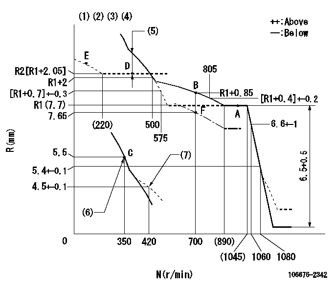
N:Pump speed
R:Rack position (mm)
(1)Lever ratio: RT
(2)Target shim dimension: TH
(3)Tolerance for racks not indicated: +-0.05mm.
(4)Boost compensator cancel stroke: BSL
(5)Boost compensator stroke: BCL
(6)Main spring setting
(7)Damper spring setting
----------
RT=1 TH=1.7mm BSL=1.6mm BCL=(1.25)mm
----------
----------
RT=1 TH=1.7mm BSL=1.6mm BCL=(1.25)mm
----------
Speed control lever angle
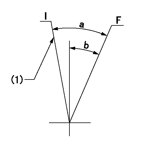
F:Full speed
I:Idle
(1)Stopper bolt setting
----------
----------
a=15.5deg+-5deg b=15deg+-5deg
----------
----------
a=15.5deg+-5deg b=15deg+-5deg
0000000901
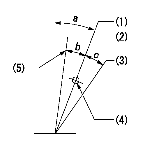
(1)Normal full load
(2)Rack position = aa, speed = bb (half load)
(3)Lever cancel angle
(4)Use the hole above R = cc
(5)Stopper bolt setting
----------
aa=7.65mm bb=700r/min cc=75mm
----------
a=10deg+-5deg b=3.5deg+-3deg c=(11.5deg)
----------
aa=7.65mm bb=700r/min cc=75mm
----------
a=10deg+-5deg b=3.5deg+-3deg c=(11.5deg)
Stop lever angle
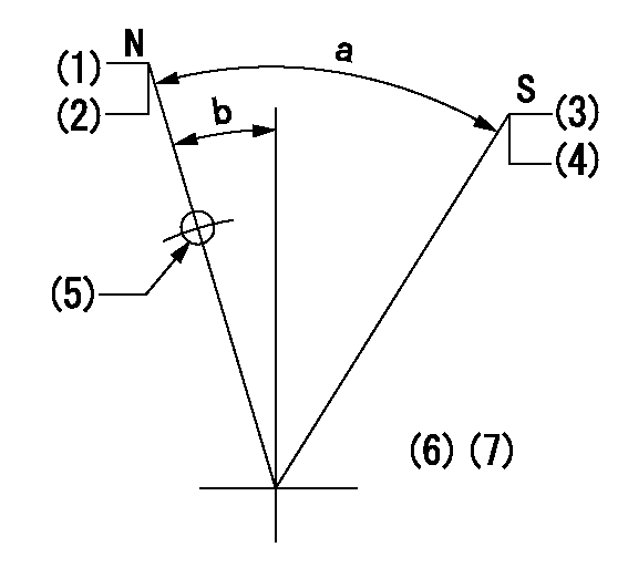
N:Pump normal
S:Stop the pump.
(1)Rack position = aa
(2)Stopper bolt setting
(3)Rack position = bb or less
(4)Stopper bolt setting
(5)Use the hole above R = cc
(6)No return spring
(7)Set the stopper bolt at the lever angle.
----------
aa=(15.3)mm bb=3.2mm cc=37mm
----------
a=40deg+-5deg b=8deg+-5deg
----------
aa=(15.3)mm bb=3.2mm cc=37mm
----------
a=40deg+-5deg b=8deg+-5deg
Timing setting

(1)Pump vertical direction
(2)Coupling's key groove position at No 1 cylinder's beginning of injection
(3)B.T.D.C.: aa
(4)-
----------
aa=12deg
----------
a=(6deg)
----------
aa=12deg
----------
a=(6deg)