
Rating:
Information injection-pump assembly
ZEXEL
106673-3340
1066733340
HINO
220206120A
220206120a
Cross reference number
ZEXEL
106673-3340
1066733340
HINO
220206120A
220206120a
Zexel num
Bosch num
Firm num
Name
Calibration Data:
Adjustment conditions
Test oil
1404 Test oil ISO4113 or {SAEJ967d}
1404 Test oil ISO4113 or {SAEJ967d}
Test oil temperature
degC
40
40
45
Nozzle and nozzle holder
105780-8140
Bosch type code
EF8511/9A
Nozzle
105780-0000
Bosch type code
DN12SD12T
Nozzle holder
105780-2080
Bosch type code
EF8511/9
Opening pressure
MPa
17.2
Opening pressure
kgf/cm2
175
Injection pipe
Outer diameter - inner diameter - length (mm) mm 8-3-600
Outer diameter - inner diameter - length (mm) mm 8-3-600
Overflow valve
134424-1420
Overflow valve opening pressure
kPa
162
147
177
Overflow valve opening pressure
kgf/cm2
1.65
1.5
1.8
Tester oil delivery pressure
kPa
157
157
157
Tester oil delivery pressure
kgf/cm2
1.6
1.6
1.6
Direction of rotation (viewed from drive side)
Right R
Right R
Injection timing adjustment
Direction of rotation (viewed from drive side)
Right R
Right R
Injection order
1-4-2-6-
3-5
Pre-stroke
mm
3.9
3.8
3.9
Beginning of injection position
Drive side NO.1
Drive side NO.1
Difference between angles 1
Cal 1-4 deg. 60 59.5 60.5
Cal 1-4 deg. 60 59.5 60.5
Difference between angles 2
Cyl.1-2 deg. 120 119.5 120.5
Cyl.1-2 deg. 120 119.5 120.5
Difference between angles 3
Cal 1-6 deg. 180 179.5 180.5
Cal 1-6 deg. 180 179.5 180.5
Difference between angles 4
Cal 1-3 deg. 240 239.5 240.5
Cal 1-3 deg. 240 239.5 240.5
Difference between angles 5
Cal 1-5 deg. 300 299.5 300.5
Cal 1-5 deg. 300 299.5 300.5
Injection quantity adjustment
Adjusting point
A
Rack position
10.6
Pump speed
r/min
700
700
700
Average injection quantity
mm3/st.
154.5
152.5
156.5
Max. variation between cylinders
%
0
-3
3
Basic
*
Fixing the lever
*
Boost pressure
kPa
48
48
Boost pressure
mmHg
360
360
Injection quantity adjustment_02
Adjusting point
C
Rack position
5.8+-0.5
Pump speed
r/min
400
400
400
Average injection quantity
mm3/st.
13.5
10.5
16.5
Max. variation between cylinders
%
0
-15
15
Fixing the rack
*
Boost pressure
kPa
0
0
0
Boost pressure
mmHg
0
0
0
Injection quantity adjustment_03
Adjusting point
E
Rack position
10.8++
Pump speed
r/min
100
100
100
Average injection quantity
mm3/st.
140
135
145
Fixing the lever
*
Boost pressure
kPa
0
0
0
Boost pressure
mmHg
0
0
0
Rack limit
*
Boost compensator adjustment
Pump speed
r/min
600
600
600
Rack position
R1-1.95
Boost pressure
kPa
4
4
6
Boost pressure
mmHg
30
30
45
Boost compensator adjustment_02
Pump speed
r/min
600
600
600
Rack position
R1(10.6)
Boost pressure
kPa
34.7
34.7
34.7
Boost pressure
mmHg
260
260
260
Timer adjustment
Pump speed
r/min
[N1+50]-
-
Advance angle
deg.
0
0
0
Remarks
Start
Start
Timer adjustment_02
Pump speed
r/min
N1
Advance angle
deg.
0.3
Remarks
Measure the actual speed.
Measure the actual speed.
Timer adjustment_03
Pump speed
r/min
-
Advance angle
deg.
1.5
1.2
1.8
Remarks
Measure the actual speed.
Measure the actual speed.
Timer adjustment_04
Pump speed
r/min
(1100)
Advance angle
deg.
2
1.5
2.5
Remarks
Finish
Finish
Test data Ex:
Governor adjustment
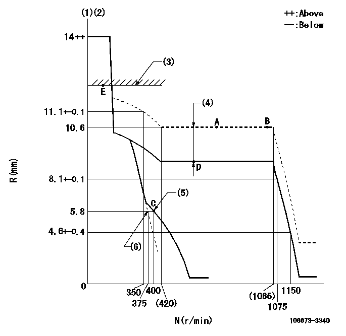
N:Pump speed
R:Rack position (mm)
(1)Target notch: K
(2)Tolerance for racks not indicated: +-0.05mm.
(3)RACK LIMIT
(4)Boost compensator stroke: BCL
(5)Set idle sub-spring
(6)Main spring setting
----------
K=10 BCL=1.95+-0.1mm
----------
----------
K=10 BCL=1.95+-0.1mm
----------
Speed control lever angle
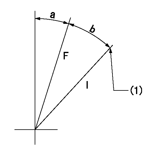
F:Full speed
I:Idle
(1)Stopper bolt setting
----------
----------
a=2deg+-5deg b=18deg+-5deg
----------
----------
a=2deg+-5deg b=18deg+-5deg
Stop lever angle
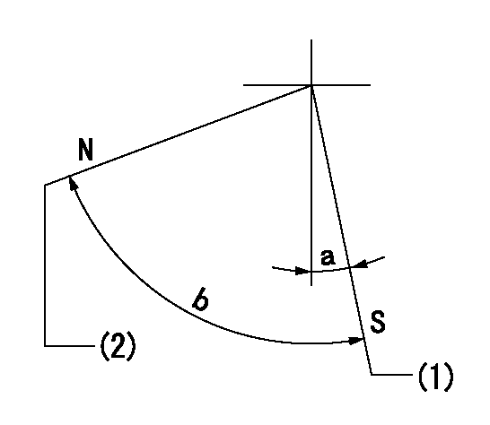
N:Pump normal
S:Stop the pump.
(1)Pump speed aa and rack position bb (to be sealed at delivery)
(2)Normal
----------
aa=0r/min bb=1-0.5mm
----------
a=10deg+-5deg b=70deg+-5deg
----------
aa=0r/min bb=1-0.5mm
----------
a=10deg+-5deg b=70deg+-5deg
0000001501 TAMPER PROOF
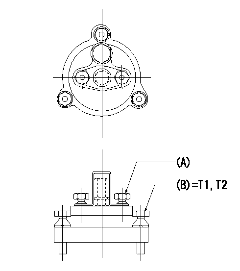
Tamperproofing-equipped boost compensator cover installation procedure
(A): After adjusting the boost compensator, assemble then tighten the bolts to remove the heads.
(B): Specified torque
(1)Before adjusting the governor and the boost compensator, tighten the screw to the specified torque.
(Tightening torque T = T1 maximum)
(2)After adjusting the governor and the boost compensator, tighten to the specified torque to break off the bolt heads.
(Tightening torque T = T2)
----------
T1=2.5N-m(0.25kgf-m) T2=2.9~4.4N-m(0.3~0.45kgf-m)
----------
----------
T1=2.5N-m(0.25kgf-m) T2=2.9~4.4N-m(0.3~0.45kgf-m)
----------
Timing setting
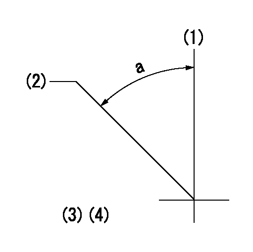
(1)Pump vertical direction
(2)Coupling's key groove position at No 1 cylinder's beginning of injection
(3)-
(4)-
----------
----------
a=(50deg)
----------
----------
a=(50deg)