
Rating:
Information injection-pump assembly
BOSCH
F 019 Z10 128
f019z10128
ZEXEL
106673-3290
1066733290
Service parts 106673-3290 INJECTION-PUMP ASSEMBLY:
1.
_
7.
COUPLING PLATE
8.
_
9.
_
11.
Nozzle and Holder
12.
Open Pre:MPa(Kqf/cm2)
21.6{220}

15.
NOZZLE SET
Include in #1:
106673-3290
as INJECTION-PUMP ASSEMBLY
Cross reference number
BOSCH
F 019 Z10 128
f019z10128
ZEXEL
106673-3290
1066733290
Zexel num
Bosch num
Firm num
Name
Calibration Data:
Adjustment conditions
Test oil
1404 Test oil ISO4113 or {SAEJ967d}
1404 Test oil ISO4113 or {SAEJ967d}
Test oil temperature
degC
40
40
45
Nozzle and nozzle holder
105780-8140
Bosch type code
EF8511/9A
Nozzle
105780-0000
Bosch type code
DN12SD12T
Nozzle holder
105780-2080
Bosch type code
EF8511/9
Opening pressure
MPa
17.2
Opening pressure
kgf/cm2
175
Injection pipe
Outer diameter - inner diameter - length (mm) mm 8-3-600
Outer diameter - inner diameter - length (mm) mm 8-3-600
Overflow valve
134424-0920
Overflow valve opening pressure
kPa
162
147
177
Overflow valve opening pressure
kgf/cm2
1.65
1.5
1.8
Tester oil delivery pressure
kPa
157
157
157
Tester oil delivery pressure
kgf/cm2
1.6
1.6
1.6
Direction of rotation (viewed from drive side)
Left L
Left L
Injection timing adjustment
Direction of rotation (viewed from drive side)
Left L
Left L
Injection order
1-4-2-6-
3-5
Pre-stroke
mm
3.9
3.84
3.9
Beginning of injection position
Drive side NO.1
Drive side NO.1
Difference between angles 1
Cal 1-4 deg. 60 59.75 60.25
Cal 1-4 deg. 60 59.75 60.25
Difference between angles 2
Cyl.1-2 deg. 120 119.75 120.25
Cyl.1-2 deg. 120 119.75 120.25
Difference between angles 3
Cal 1-6 deg. 180 179.75 180.25
Cal 1-6 deg. 180 179.75 180.25
Difference between angles 4
Cal 1-3 deg. 240 239.75 240.25
Cal 1-3 deg. 240 239.75 240.25
Difference between angles 5
Cal 1-5 deg. 300 299.75 300.25
Cal 1-5 deg. 300 299.75 300.25
Injection quantity adjustment
Adjusting point
A
Rack position
11.5
Pump speed
r/min
1000
1000
1000
Average injection quantity
mm3/st.
208
206
210
Max. variation between cylinders
%
0
-2
2
Basic
*
Fixing the lever
*
Boost pressure
kPa
62
62
Boost pressure
mmHg
465
465
Injection quantity adjustment_02
Adjusting point
C
Rack position
5.2+-0.5
Pump speed
r/min
550
550
550
Average injection quantity
mm3/st.
12
9
15
Max. variation between cylinders
%
0
-15
15
Fixing the rack
*
Boost pressure
kPa
0
0
0
Boost pressure
mmHg
0
0
0
Injection quantity adjustment_03
Adjusting point
D
Rack position
-
Pump speed
r/min
100
100
100
Average injection quantity
mm3/st.
165
165
175
Fixing the lever
*
Boost pressure
kPa
0
0
0
Boost pressure
mmHg
0
0
0
Rack limit
*
Boost compensator adjustment
Pump speed
r/min
600
600
600
Rack position
R1-1.6
Boost pressure
kPa
20.7
18
23.4
Boost pressure
mmHg
155
135
175
Boost compensator adjustment_02
Pump speed
r/min
600
600
600
Rack position
R1(11.5)
Boost pressure
kPa
50
44.7
55.3
Boost pressure
mmHg
375
335
415
Timer adjustment
Pump speed
r/min
750--
Advance angle
deg.
0
0
0
Load
3/4
Remarks
Start
Start
Timer adjustment_02
Pump speed
r/min
700
Advance angle
deg.
0.3
Load
4/4
Timer adjustment_03
Pump speed
r/min
1000
Advance angle
deg.
3
2.7
3.3
Load
4/4
Remarks
Finish
Finish
Test data Ex:
Governor adjustment
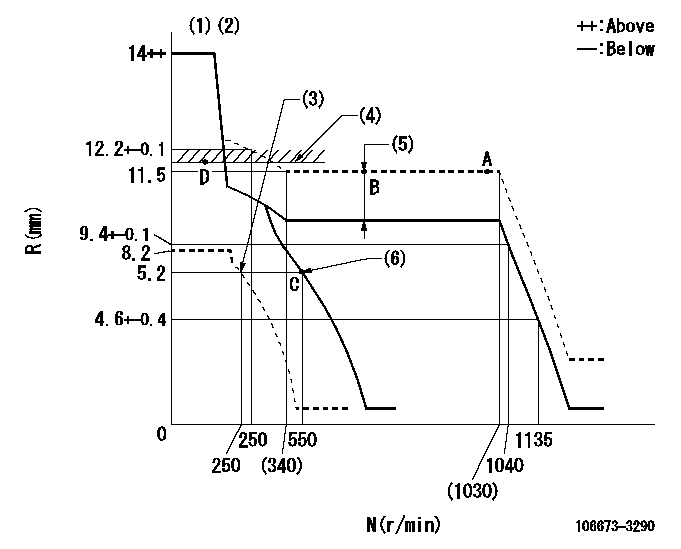
N:Pump speed
R:Rack position (mm)
(1)Target notch: K
(2)Tolerance for racks not indicated: +-0.05mm.
(3)Set idle sub-spring
(4)RACK LIMIT
(5)Boost compensator stroke: BCL
(6)Main spring setting
----------
K=16 BCL=1.6+-0.1mm
----------
----------
K=16 BCL=1.6+-0.1mm
----------
Speed control lever angle
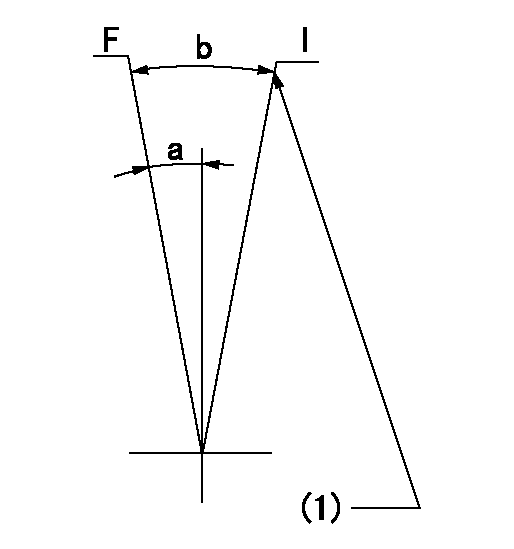
F:Full speed
I:Idle
(1)Stopper bolt setting
----------
----------
a=6deg+-5deg b=17deg+-5deg
----------
----------
a=6deg+-5deg b=17deg+-5deg
Stop lever angle
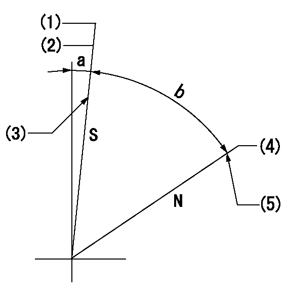
N:Pump normal
S:Stop the pump.
(1)Pump speed aa and rack position bb (to be sealed at delivery)
(2)Normal stop
(3)Stopper bolt setting
(4)Rack position corresponding to cc (seal at delivery)
(5)Stopper bolt setting
----------
aa=0r/min bb=2.5-0.5mm cc=19.5mm
----------
a=5deg+-5deg b=55deg+-5deg
----------
aa=0r/min bb=2.5-0.5mm cc=19.5mm
----------
a=5deg+-5deg b=55deg+-5deg
Timing setting

(1)Pump vertical direction
(2)Coupling's key groove position at No 1 cylinder's beginning of injection
(3)-
(4)-
----------
----------
a=(0deg)
----------
----------
a=(0deg)