Rating:
Information injection-pump assembly
BOSCH
F 01G 09U 08K
f01g09u08k
ZEXEL
106673-2380
1066732380
Service parts 106673-2380 INJECTION-PUMP ASSEMBLY:
1.
_
7.
COUPLING PLATE
8.
_
9.
_
11.
Nozzle and Holder
ME050883
12.
Open Pre:MPa(Kqf/cm2)
21.6{220}

15.
NOZZLE SET
Include in #1:
106673-2380
as INJECTION-PUMP ASSEMBLY
Cross reference number
BOSCH
F 01G 09U 08K
f01g09u08k
ZEXEL
106673-2380
1066732380
Zexel num
Bosch num
Firm num
Name
Calibration Data:
Adjustment conditions
Test oil
1404 Test oil ISO4113 or {SAEJ967d}
1404 Test oil ISO4113 or {SAEJ967d}
Test oil temperature
degC
40
40
45
Nozzle and nozzle holder
105780-8140
Bosch type code
EF8511/9A
Nozzle
105780-0000
Bosch type code
DN12SD12T
Nozzle holder
105780-2080
Bosch type code
EF8511/9
Opening pressure
MPa
17.2
Opening pressure
kgf/cm2
175
Injection pipe
Outer diameter - inner diameter - length (mm) mm 8-3-600
Outer diameter - inner diameter - length (mm) mm 8-3-600
Overflow valve
131424-4620
Overflow valve opening pressure
kPa
255
221
289
Overflow valve opening pressure
kgf/cm2
2.6
2.25
2.95
Tester oil delivery pressure
kPa
157
157
157
Tester oil delivery pressure
kgf/cm2
1.6
1.6
1.6
Direction of rotation (viewed from drive side)
Right R
Right R
Injection timing adjustment
Direction of rotation (viewed from drive side)
Right R
Right R
Injection order
1-5-3-6-
2-4
Pre-stroke
mm
4.8
4.75
4.85
Beginning of injection position
Governor side NO.1
Governor side NO.1
Difference between angles 1
Cal 1-5 deg. 60 59.5 60.5
Cal 1-5 deg. 60 59.5 60.5
Difference between angles 2
Cal 1-3 deg. 120 119.5 120.5
Cal 1-3 deg. 120 119.5 120.5
Difference between angles 3
Cal 1-6 deg. 180 179.5 180.5
Cal 1-6 deg. 180 179.5 180.5
Difference between angles 4
Cyl.1-2 deg. 240 239.5 240.5
Cyl.1-2 deg. 240 239.5 240.5
Difference between angles 5
Cal 1-4 deg. 300 299.5 300.5
Cal 1-4 deg. 300 299.5 300.5
Injection quantity adjustment
Adjusting point
A
Rack position
10.5
Pump speed
r/min
800
800
800
Average injection quantity
mm3/st.
145.3
142.3
148.3
Max. variation between cylinders
%
0
-3
3
Basic
*
Fixing the lever
*
Boost pressure
kPa
49.3
49.3
Boost pressure
mmHg
370
370
Injection quantity adjustment_02
Adjusting point
B
Rack position
5.8+-0.5
Pump speed
r/min
275
275
275
Average injection quantity
mm3/st.
15
12.4
17.6
Fixing the rack
*
Boost pressure
kPa
0
0
0
Boost pressure
mmHg
0
0
0
Remarks
(check)
(check)
Injection quantity adjustment_03
Adjusting point
C
Rack position
5.2+-0.5
Pump speed
r/min
500
500
500
Average injection quantity
mm3/st.
15
12.4
17.6
Max. variation between cylinders
%
0
-15
15
Fixing the rack
*
Boost pressure
kPa
0
0
0
Boost pressure
mmHg
0
0
0
Injection quantity adjustment_04
Adjusting point
D
Rack position
12+0.2
Pump speed
r/min
100
100
100
Average injection quantity
mm3/st.
142
122
162
Fixing the lever
*
Boost pressure
kPa
0
0
0
Boost pressure
mmHg
0
0
0
Rack limit
*
Boost compensator adjustment
Pump speed
r/min
600
600
600
Rack position
9.3
Boost pressure
kPa
6.7
5.4
8
Boost pressure
mmHg
50
40
60
Boost compensator adjustment_02
Pump speed
r/min
600
600
600
Rack position
10.5
Boost pressure
kPa
36
29.3
42.7
Boost pressure
mmHg
270
220
320
Timer adjustment
Pump speed
r/min
950--
Advance angle
deg.
0
0
0
Remarks
Start
Start
Timer adjustment_02
Pump speed
r/min
900
Advance angle
deg.
0.5
Timer adjustment_03
Pump speed
r/min
1100
Advance angle
deg.
1.5
1
2
Remarks
Finish
Finish
Test data Ex:
Governor adjustment
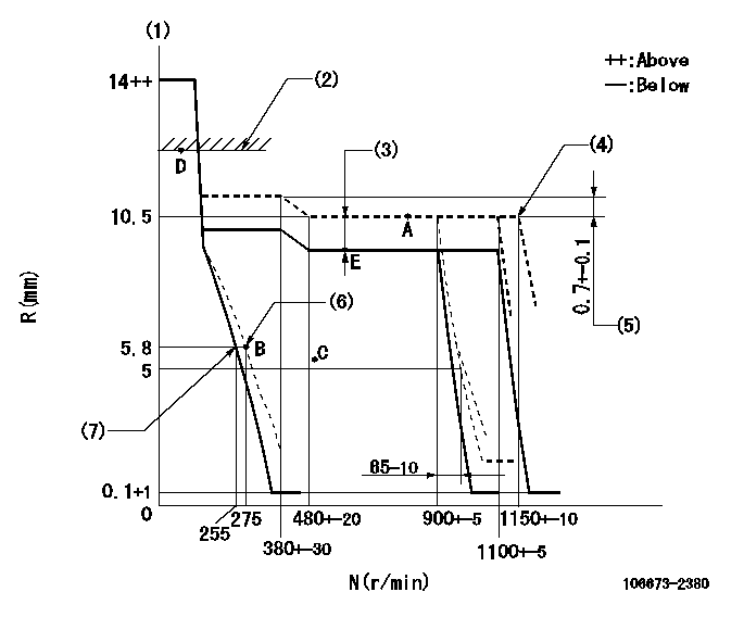
N:Pump speed
R:Rack position (mm)
(1)Target notch: K
(2)RACK LIMIT
(3)Boost compensator stroke: BCL
(4)At shipping
(5)Rack difference between N = N1 and N = N2
(6)Set idle sub-spring
(7)Main spring setting
----------
K=8 BCL=1.2+-0.1mm N1=800r/min N2=300r/min
----------
----------
K=8 BCL=1.2+-0.1mm N1=800r/min N2=300r/min
----------
Speed control lever angle
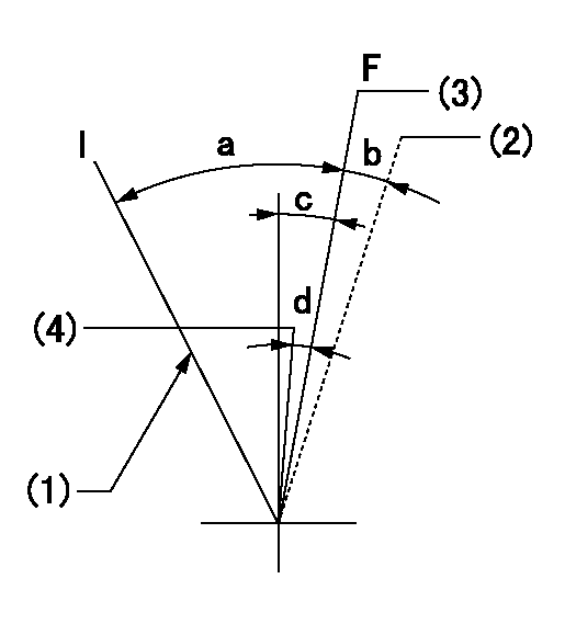
F:Full speed
I:Idle
(1)Stopper bolt setting
(2)At shipping
(3)Set the pump speed at aa
(4)Set the pump speed at bb.
----------
aa=1100r/min bb=900r/min
----------
a=(27deg)+-5deg b=(2deg) c=(8deg)+-5deg d=(7deg)+-5deg
----------
aa=1100r/min bb=900r/min
----------
a=(27deg)+-5deg b=(2deg) c=(8deg)+-5deg d=(7deg)+-5deg
Stop lever angle
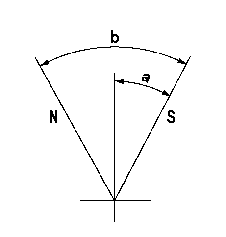
N:Pump normal
S:Stop the pump.
----------
----------
a=50deg+-5deg b=70deg+-5deg
----------
----------
a=50deg+-5deg b=70deg+-5deg
Timing setting

(1)Pump vertical direction
(2)Coupling's key groove position at No 1 cylinder's beginning of injection
(3)-
(4)-
----------
----------
a=(3deg)
----------
----------
a=(3deg)