
Rating:
Information injection-pump assembly
BOSCH
9 400 617 156
9400617156
ZEXEL
106672-9303
1066729303
KOMATSU
6151711323
6151711323
Service parts 106672-9303 INJECTION-PUMP ASSEMBLY:
1.
_
5.
AUTOM. ADVANCE MECHANIS
7.
COUPLING PLATE
8.
_
9.
_
11.
Nozzle and Holder
6151-11-3101
12.
Open Pre:MPa(Kqf/cm2)
24.5{250}
15.
NOZZLE SET
Include in #1:
106672-9303
as INJECTION-PUMP ASSEMBLY
Cross reference number
BOSCH
9 400 617 156
9400617156
ZEXEL
106672-9303
1066729303
KOMATSU
6151711323
6151711323
Zexel num
Bosch num
Firm num
Name
9 400 617 156
6151711323 KOMATSU
INJECTION-PUMP ASSEMBLY
S6D125 K 14CA INJECTION PUMP ASSY PE6P,6PD PE
S6D125 K 14CA INJECTION PUMP ASSY PE6P,6PD PE
Calibration Data:
Adjustment conditions
Test oil
1404 Test oil ISO4113 or {SAEJ967d}
1404 Test oil ISO4113 or {SAEJ967d}
Test oil temperature
degC
40
40
45
Nozzle and nozzle holder
105780-8140
Bosch type code
EF8511/9A
Nozzle
105780-0000
Bosch type code
DN12SD12T
Nozzle holder
105780-2080
Bosch type code
EF8511/9
Opening pressure
MPa
17.2
Opening pressure
kgf/cm2
175
Injection pipe
Outer diameter - inner diameter - length (mm) mm 8-3-600
Outer diameter - inner diameter - length (mm) mm 8-3-600
Overflow valve opening pressure
kPa
157
157
157
Overflow valve opening pressure
kgf/cm2
1.6
1.6
1.6
Tester oil delivery pressure
kPa
157
157
157
Tester oil delivery pressure
kgf/cm2
1.6
1.6
1.6
Direction of rotation (viewed from drive side)
Left L
Left L
Injection timing adjustment
Direction of rotation (viewed from drive side)
Left L
Left L
Injection order
1-5-3-6-
2-4
Pre-stroke
mm
3.8
3.75
3.85
Beginning of injection position
Drive side NO.1
Drive side NO.1
Difference between angles 1
Cal 1-5 deg. 60 59.5 60.5
Cal 1-5 deg. 60 59.5 60.5
Difference between angles 2
Cal 1-3 deg. 120 119.5 120.5
Cal 1-3 deg. 120 119.5 120.5
Difference between angles 3
Cal 1-6 deg. 180 179.5 180.5
Cal 1-6 deg. 180 179.5 180.5
Difference between angles 4
Cyl.1-2 deg. 240 239.5 240.5
Cyl.1-2 deg. 240 239.5 240.5
Difference between angles 5
Cal 1-4 deg. 300 299.5 300.5
Cal 1-4 deg. 300 299.5 300.5
Injection quantity adjustment
Adjusting point
A
Rack position
9.7
Pump speed
r/min
1050
1050
1050
Average injection quantity
mm3/st.
146
144
148
Max. variation between cylinders
%
0
-3
3
Basic
*
Fixing the lever
*
Boost pressure
kPa
41.3
41.3
Boost pressure
mmHg
310
310
Injection quantity adjustment_02
Adjusting point
B
Rack position
10.8+-0.
5
Pump speed
r/min
700
700
700
Average injection quantity
mm3/st.
175.3
173.3
177.3
Max. variation between cylinders
%
0
-4
4
Fixing the lever
*
Boost pressure
kPa
41.3
41.3
Boost pressure
mmHg
310
310
Injection quantity adjustment_03
Adjusting point
C
Rack position
3.6+-0.5
Pump speed
r/min
375
375
375
Average injection quantity
mm3/st.
13.3
11.8
14.8
Max. variation between cylinders
%
0
-15
15
Fixing the rack
*
Boost pressure
kPa
0
0
0
Boost pressure
mmHg
0
0
0
Boost compensator adjustment
Pump speed
r/min
500
500
500
Rack position
8.5
Boost pressure
kPa
6.7
5.4
8
Boost pressure
mmHg
50
40
60
Boost compensator adjustment_02
Pump speed
r/min
500
500
500
Rack position
10.9
Boost pressure
kPa
28
21.3
34.7
Boost pressure
mmHg
210
160
260
Test data Ex:
Governor adjustment
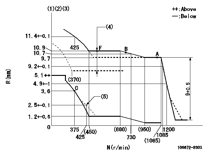
N:Pump speed
R:Rack position (mm)
(1)Lever ratio: RT
(2)Target shim dimension: TH
(3)Tolerance for racks not indicated: +-0.05mm.
(4)Boost compensator stroke: BCL
(5)Damper spring setting
----------
RT=1 TH=3.2mm BCL=2.4+-0.1mm
----------
----------
RT=1 TH=3.2mm BCL=2.4+-0.1mm
----------
Speed control lever angle

F:Full speed
----------
----------
a=19deg+-5deg
----------
----------
a=19deg+-5deg
0000000901
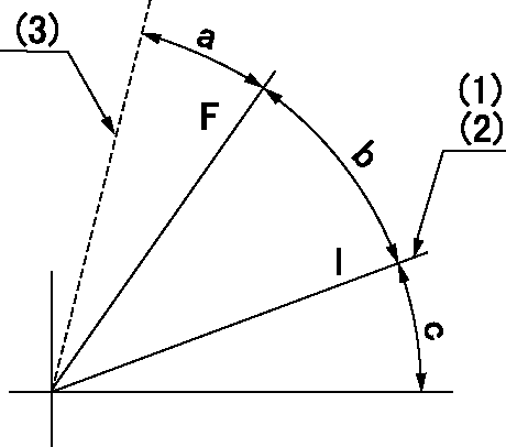
F:Full load
I:Idle
(1)Stopper bolt setting
(2)Use the pin at R = aa
(3)When load lever is cancelled.
----------
aa=50mm
----------
a=(8deg) b=36deg+-3deg c=24deg+-5deg
----------
aa=50mm
----------
a=(8deg) b=36deg+-3deg c=24deg+-5deg
Stop lever angle
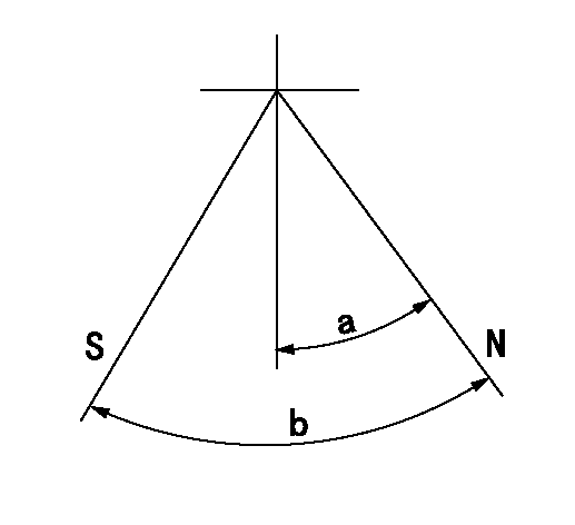
N:Pump normal
S:Stop the pump.
----------
----------
a=32deg+-5deg b=64deg+-5deg
----------
----------
a=32deg+-5deg b=64deg+-5deg
Timing setting
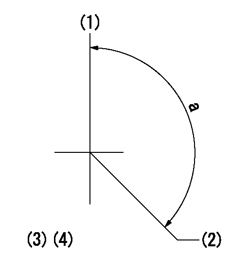
(1)Pump vertical direction
(2)Coupling's key groove position at No 1 cylinder's beginning of injection
(3)-
(4)-
----------
----------
a=(150deg)
----------
----------
a=(150deg)