Rating:
Information injection-pump assembly
BOSCH
9 400 613 008
9400613008
ZEXEL
106671-6452
1066716452
ISUZU
1156033342
1156033342
Compare Prices: .
As an associate, we earn commssions on qualifying purchases through the links below

$2,616.49
13 May 2023
0.0022[0.00] Pounds
CN: 68768Mall
Engine Fuel Pump Compatible with Isuzu 6HK1 Fuel Injection Pump 1156033345 1156033342 Engine Parts
EYLLEK ⭐ Guide rod design is adopted to maintain correct alignment and reduce clamping. || ⭐ Include a fuel tank and a jet pump to prevent the fuel pump from being insufficient when the fuel level is low. || ⭐ Most filters are placed inside the module to help reduce the chance of perforation. || ⭐ Include a fuel tank and a jet pump to prevent the fuel pump from being insufficient when the fuel level is low. || ⭐ High stability and durability: Using precision injection molding technology, our advanced plastics make the fuel pump more stable and corrosion-resistant, and will not warp as easily as other inferior plastics.
EYLLEK ⭐ Guide rod design is adopted to maintain correct alignment and reduce clamping. || ⭐ Include a fuel tank and a jet pump to prevent the fuel pump from being insufficient when the fuel level is low. || ⭐ Most filters are placed inside the module to help reduce the chance of perforation. || ⭐ Include a fuel tank and a jet pump to prevent the fuel pump from being insufficient when the fuel level is low. || ⭐ High stability and durability: Using precision injection molding technology, our advanced plastics make the fuel pump more stable and corrosion-resistant, and will not warp as easily as other inferior plastics.

$2,660.00
27 Jan 2023
CN: 广州伟烨机械配件
High Performance Diesel Engine Part ZX330 6HK1 Excavator Fuel Injection Pump 1-15603334-5 106671-6452
MUMAGI ★ Part number:1-15603334-5 106671-6452 || ★ Applicable model:t ZAX330 6HK1 Engine || ★Delivery: we will deliver goods from China through DHL / FedEx / UPS within 1-3 days and arrive within 3-7 days after delivery. || ★NOTE:Before placing an order, please pay attention to check whether the accessories of your car are consistent with the appearance and part number of this product
MUMAGI ★ Part number:1-15603334-5 106671-6452 || ★ Applicable model:t ZAX330 6HK1 Engine || ★Delivery: we will deliver goods from China through DHL / FedEx / UPS within 1-3 days and arrive within 3-7 days after delivery. || ★NOTE:Before placing an order, please pay attention to check whether the accessories of your car are consistent with the appearance and part number of this product
Service parts 106671-6452 INJECTION-PUMP ASSEMBLY:
1.
_

7.
COUPLING PLATE
8.
_
9.
_
11.
Nozzle and Holder
1-15300-389-1
12.
Open Pre:MPa(Kqf/cm2)
18.1{185}/22.1{225}
14.
NOZZLE
Include in #1:
106671-6452
as INJECTION-PUMP ASSEMBLY
Cross reference number
BOSCH
9 400 613 008
9400613008
ZEXEL
106671-6452
1066716452
ISUZU
1156033342
1156033342
Zexel num
Bosch num
Firm num
Name
106671-6452
9 400 613 008
1156033342 ISUZU
INJECTION-PUMP ASSEMBLY
6HK1-XQA K 14CA INJECTION PUMP ASSY PE6P,6PD PE
6HK1-XQA K 14CA INJECTION PUMP ASSY PE6P,6PD PE
Calibration Data:
Adjustment conditions
Test oil
1404 Test oil ISO4113 or {SAEJ967d}
1404 Test oil ISO4113 or {SAEJ967d}
Test oil temperature
degC
40
40
45
Nozzle and nozzle holder
105780-8140
Bosch type code
EF8511/9A
Nozzle
105780-0000
Bosch type code
DN12SD12T
Nozzle holder
105780-2080
Bosch type code
EF8511/9
Opening pressure
MPa
17.2
Opening pressure
kgf/cm2
175
Injection pipe
Outer diameter - inner diameter - length (mm) mm 8-3-600
Outer diameter - inner diameter - length (mm) mm 8-3-600
Overflow valve
134424-4320
Overflow valve opening pressure
kPa
255
221
289
Overflow valve opening pressure
kgf/cm2
2.6
2.25
2.95
Tester oil delivery pressure
kPa
255
255
255
Tester oil delivery pressure
kgf/cm2
2.6
2.6
2.6
Direction of rotation (viewed from drive side)
Left L
Left L
Injection timing adjustment
Direction of rotation (viewed from drive side)
Left L
Left L
Injection order
1-5-3-6-
2-4
Pre-stroke
mm
2.9
2.87
2.93
Beginning of injection position
Governor side NO.1
Governor side NO.1
Difference between angles 1
Cal 1-5 deg. 60 59.75 60.25
Cal 1-5 deg. 60 59.75 60.25
Difference between angles 2
Cal 1-3 deg. 120 119.75 120.25
Cal 1-3 deg. 120 119.75 120.25
Difference between angles 3
Cal 1-6 deg. 180 179.75 180.25
Cal 1-6 deg. 180 179.75 180.25
Difference between angles 4
Cyl.1-2 deg. 240 239.75 240.25
Cyl.1-2 deg. 240 239.75 240.25
Difference between angles 5
Cal 1-4 deg. 300 299.75 300.25
Cal 1-4 deg. 300 299.75 300.25
Injection quantity adjustment
Adjusting point
A
Rack position
12.8
Pump speed
r/min
1000
1000
1000
Average injection quantity
mm3/st.
133.5
132.5
134.5
Max. variation between cylinders
%
0
-3
3
Basic
*
Fixing the lever
*
Boost pressure
kPa
171
171
Boost pressure
mmHg
1280
1280
Injection quantity adjustment_02
Adjusting point
-
Rack position
7.5+-0.5
Pump speed
r/min
500
500
500
Average injection quantity
mm3/st.
9.5
6.3
12.7
Max. variation between cylinders
%
0
-15
15
Fixing the rack
*
Boost pressure
kPa
0
0
0
Boost pressure
mmHg
0
0
0
Remarks
Adjust only variation between cylinders; adjust governor according to governor specifications.
Adjust only variation between cylinders; adjust governor according to governor specifications.
Injection quantity adjustment_03
Adjusting point
E
Rack position
13++
Pump speed
r/min
100
100
100
Average injection quantity
mm3/st.
155
145
165
Fixing the lever
*
Boost pressure
kPa
0
0
0
Boost pressure
mmHg
0
0
0
Rack limit
*
Boost compensator adjustment
Pump speed
r/min
550
550
550
Rack position
10.8
Boost pressure
kPa
92
88
96
Boost pressure
mmHg
690
660
720
Boost compensator adjustment_02
Pump speed
r/min
550
550
550
Rack position
11.2
Boost pressure
kPa
157
150.3
163.7
Boost pressure
mmHg
1180
1130
1230
Timer adjustment
Pump speed
r/min
1200++
Advance angle
deg.
0
0
0
Remarks
Do not advance until starting N = 1200.
Do not advance until starting N = 1200.
Timer adjustment_02
Pump speed
r/min
-
Advance angle
deg.
0.7
0.7
0.7
Remarks
Measure the actual speed, stop
Measure the actual speed, stop
Test data Ex:
Governor adjustment
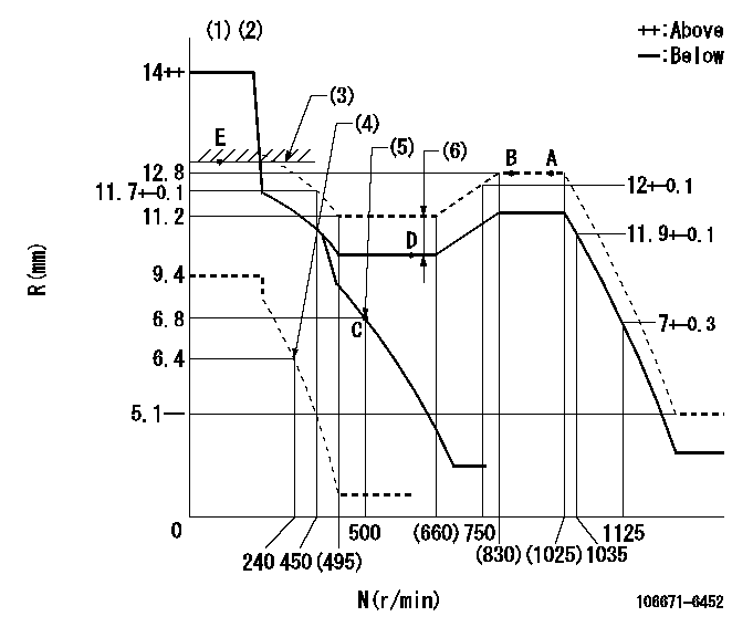
N:Pump speed
R:Rack position (mm)
(1)Target notch: K
(2)Tolerance for racks not indicated: +-0.05mm.
(3)RACK LIMIT
(4)Set idle sub-spring
(5)Main spring setting
(6)Boost compensator stroke: BCL
----------
K=12 BCL=0.4+-0.1mm
----------
----------
K=12 BCL=0.4+-0.1mm
----------
Speed control lever angle
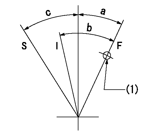
F:Full speed
I:Idle
S:Stop
(1)Use the hole at R = aa
----------
aa=70mm
----------
a=3deg+-5deg b=18deg+-5deg c=31deg+-3deg
----------
aa=70mm
----------
a=3deg+-5deg b=18deg+-5deg c=31deg+-3deg
Stop lever angle
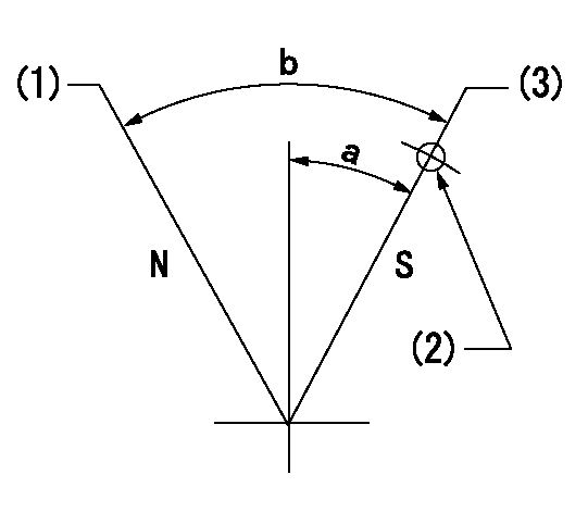
N:Pump normal
S:Stop the pump.
(1)Normal
(2)Use the hole at R = aa
(3)Rack position bb, pump speed cc (seal at delivery)
----------
aa=23mm bb=1-0.5mm cc=0r/min
----------
a=15deg+-5deg b=70deg+-5deg
----------
aa=23mm bb=1-0.5mm cc=0r/min
----------
a=15deg+-5deg b=70deg+-5deg
0000001501 TAMPER PROOF
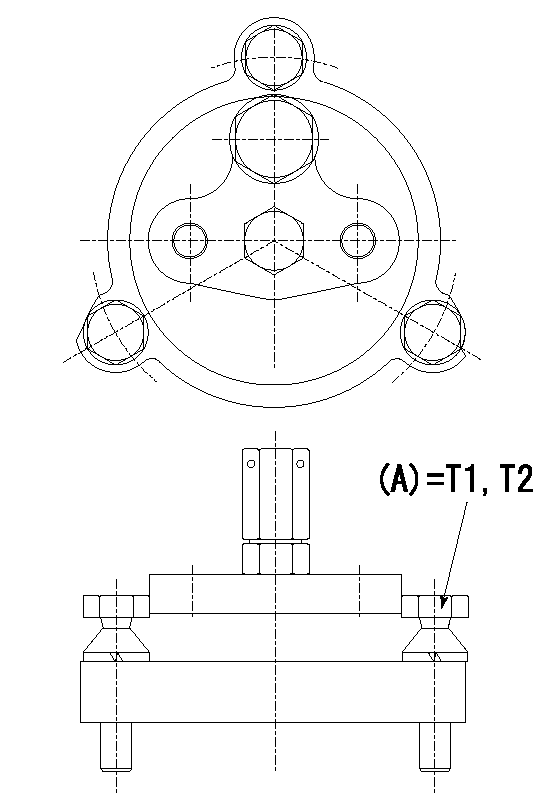
Tamperproofing-equipped boost compensator cover installation procedure
(A) After adjusting the boost compensator, tighten the bolts to remove the heads.
(1)Before adjusting the governor and the boost compensator, tighten the screw to the specified torque.
(Tightening torque T = T1 maximum)
(2)After adjusting the governor and the boost compensator, tighten to the specified torque to break off the bolt heads.
(Tightening torque T = T2)
----------
T1=2.5N-m(0.25kgf-m) T2=2.9~4.4N-m(0.3~0.45kgf-m)
----------
----------
T1=2.5N-m(0.25kgf-m) T2=2.9~4.4N-m(0.3~0.45kgf-m)
----------
Timing setting

(1)Pump vertical direction
(2)Position of timer's threaded installation hole at No 1 cylinder's beginning of injection
(3)B.T.D.C.: aa
(4)-
----------
aa=9deg
----------
a=(50deg)
----------
aa=9deg
----------
a=(50deg)
Have questions with 106671-6452?
Group cross 106671-6452 ZEXEL
Isuzu
Isuzu
106671-6452
9 400 613 008
1156033342
INJECTION-PUMP ASSEMBLY
6HK1-XQA
6HK1-XQA