Rating:
Information injection-pump assembly
ZEXEL
106671-3910
1066713910
HINO
220004650A
220004650a
Service parts 106671-3910 INJECTION-PUMP ASSEMBLY:
1.
_
7.
COUPLING PLATE
8.
_
9.
_
11.
Nozzle and Holder
23600-1690
12.
Open Pre:MPa(Kqf/cm2)
14.7{150}/21.6{220}

15.
NOZZLE SET
Include in #1:
106671-3910
as INJECTION-PUMP ASSEMBLY
Cross reference number
ZEXEL
106671-3910
1066713910
HINO
220004650A
220004650a
Zexel num
Bosch num
Firm num
Name
Calibration Data:
Adjustment conditions
Test oil
1404 Test oil ISO4113 or {SAEJ967d}
1404 Test oil ISO4113 or {SAEJ967d}
Test oil temperature
degC
40
40
45
Nozzle and nozzle holder
105780-8140
Bosch type code
EF8511/9A
Nozzle
105780-0000
Bosch type code
DN12SD12T
Nozzle holder
105780-2080
Bosch type code
EF8511/9
Opening pressure
MPa
17.2
Opening pressure
kgf/cm2
175
Injection pipe
Outer diameter - inner diameter - length (mm) mm 8-3-600
Outer diameter - inner diameter - length (mm) mm 8-3-600
Overflow valve
134424-0920
Overflow valve opening pressure
kPa
162
147
177
Overflow valve opening pressure
kgf/cm2
1.65
1.5
1.8
Tester oil delivery pressure
kPa
157
157
157
Tester oil delivery pressure
kgf/cm2
1.6
1.6
1.6
Direction of rotation (viewed from drive side)
Left L
Left L
Injection timing adjustment
Direction of rotation (viewed from drive side)
Left L
Left L
Injection order
1-4-2-6-
3-5
Pre-stroke
mm
4.8
4.74
4.8
Rack position
Point B R=B
Point B R=B
Beginning of injection position
Drive side NO.1
Drive side NO.1
Difference between angles 1
Cal 1-4 deg. 60 59.75 60.25
Cal 1-4 deg. 60 59.75 60.25
Difference between angles 2
Cyl.1-2 deg. 120 119.75 120.25
Cyl.1-2 deg. 120 119.75 120.25
Difference between angles 3
Cal 1-6 deg. 180 179.75 180.25
Cal 1-6 deg. 180 179.75 180.25
Difference between angles 4
Cal 1-3 deg. 240 239.75 240.25
Cal 1-3 deg. 240 239.75 240.25
Difference between angles 5
Cal 1-5 deg. 300 299.75 300.25
Cal 1-5 deg. 300 299.75 300.25
Injection quantity adjustment
Adjusting point
A
Rack position
R1(7.4)
Pump speed
r/min
500
500
500
Average injection quantity
mm3/st.
142
139
145
Max. variation between cylinders
%
0
-4
4
Fixing the lever
*
Injection quantity adjustment_02
Adjusting point
B
Rack position
7.7
Pump speed
r/min
700
700
700
Average injection quantity
mm3/st.
147
145
149
Max. variation between cylinders
%
0
-2
2
Basic
*
Fixing the lever
*
Injection quantity adjustment_03
Adjusting point
C
Rack position
7.8
Pump speed
r/min
1075
1075
1075
Average injection quantity
mm3/st.
151
145
157
Max. variation between cylinders
%
0
-4
4
Fixing the lever
*
Injection quantity adjustment_04
Adjusting point
D
Rack position
4+-0.5
Pump speed
r/min
225
225
225
Average injection quantity
mm3/st.
10
7
13
Max. variation between cylinders
%
0
-15
15
Fixing the rack
*
Test data Ex:
Governor adjustment
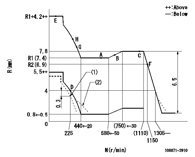
N:Pump speed
R:Rack position (mm)
(1)Set to idle at shipping.
(2)Damper spring setting: DL
----------
DL=3.5-0.2mm
----------
----------
DL=3.5-0.2mm
----------
Timer adjustment
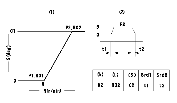
(1)Adjusting range
(2)Step response time
(N): Speed of the pump
(L): Load
(theta) Advance angle
(Srd1) Step response time 1
(Srd2) Step response time 2
1. Adjusting conditions for the variable timer
(1)Adjust the clearance between the pickup and the protrusion to L.
----------
L=1-0.2mm N2=800r/min C2=(9deg) t1=2--sec. t2=2--sec.
----------
N1=950+-50r/min P1=0kPa(0kgf/cm2) P2=392kPa(4kgf/cm2) C1=9+-0.5deg R01=0/4load R02=4/4load
----------
L=1-0.2mm N2=800r/min C2=(9deg) t1=2--sec. t2=2--sec.
----------
N1=950+-50r/min P1=0kPa(0kgf/cm2) P2=392kPa(4kgf/cm2) C1=9+-0.5deg R01=0/4load R02=4/4load
Speed control lever angle

F:Full speed
----------
----------
a=12deg+-5deg
----------
----------
a=12deg+-5deg
0000000901
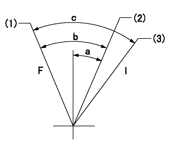
F:Full load
I:Idle
(1)Use the hole at R = aa
(2)Set point D
(3)At shipping
----------
aa=50mm
----------
a=16deg+-5deg b=35deg+-3deg c=36.5deg+-5deg
----------
aa=50mm
----------
a=16deg+-5deg b=35deg+-3deg c=36.5deg+-5deg
Stop lever angle
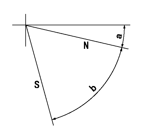
N:Pump normal
S:Stop the pump.
----------
----------
a=15deg+-5deg b=64deg+-5deg
----------
----------
a=15deg+-5deg b=64deg+-5deg
0000001501 RACK SENSOR
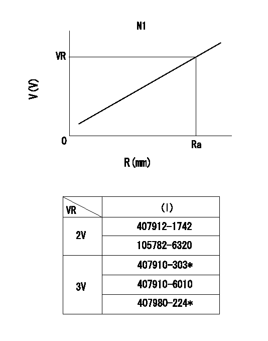
R:Rack position (mm)
V:Voltage (V)
After installing the rack sensor, confirm the output value (VR).
----------
N1=700r/min Ra=7.7mm VR=1.95+-0.01V
----------
----------
N1=700r/min Ra=7.7mm VR=1.95+-0.01V
----------
Timing setting
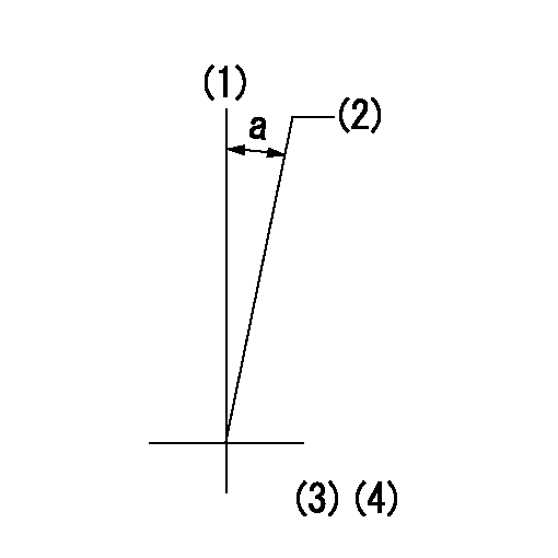
(1)Pump vertical direction
(2)Coupling's key groove position at No 1 cylinder's beginning of injection
(3)-
(4)-
----------
----------
a=(0deg)
----------
----------
a=(0deg)