Rating:
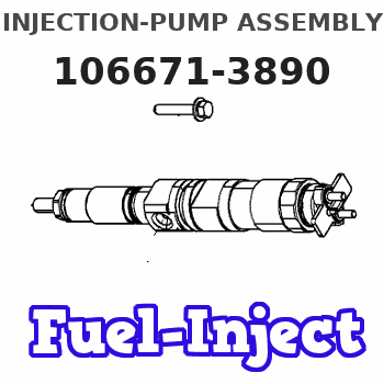
Information injection-pump assembly
BOSCH
9 400 616 783
9400616783
ZEXEL
106671-3890
1066713890
HINO
220004810A
220004810a
Service parts 106671-3890 INJECTION-PUMP ASSEMBLY:
1.
_
7.
COUPLING PLATE
8.
_
9.
_
11.
Nozzle and Holder
23600-1690
12.
Open Pre:MPa(Kqf/cm2)
14.7{150}/21.6{220}

15.
NOZZLE SET
Include in #1:
106671-3890
as INJECTION-PUMP ASSEMBLY
Cross reference number
BOSCH
9 400 616 783
9400616783
ZEXEL
106671-3890
1066713890
HINO
220004810A
220004810a
Zexel num
Bosch num
Firm num
Name
106671-3890
9 400 616 783
220004810A HINO
INJECTION-PUMP ASSEMBLY
EK100 * K 14CA PE6P,6PD PE
EK100 * K 14CA PE6P,6PD PE
Calibration Data:
Adjustment conditions
Test oil
1404 Test oil ISO4113 or {SAEJ967d}
1404 Test oil ISO4113 or {SAEJ967d}
Test oil temperature
degC
40
40
45
Nozzle and nozzle holder
105780-8140
Bosch type code
EF8511/9A
Nozzle
105780-0000
Bosch type code
DN12SD12T
Nozzle holder
105780-2080
Bosch type code
EF8511/9
Opening pressure
MPa
17.2
Opening pressure
kgf/cm2
175
Injection pipe
Outer diameter - inner diameter - length (mm) mm 8-3-600
Outer diameter - inner diameter - length (mm) mm 8-3-600
Overflow valve
134424-0920
Overflow valve opening pressure
kPa
162
147
177
Overflow valve opening pressure
kgf/cm2
1.65
1.5
1.8
Tester oil delivery pressure
kPa
157
157
157
Tester oil delivery pressure
kgf/cm2
1.6
1.6
1.6
Direction of rotation (viewed from drive side)
Left L
Left L
Injection timing adjustment
Direction of rotation (viewed from drive side)
Left L
Left L
Injection order
1-4-2-6-
3-5
Pre-stroke
mm
4.8
4.74
4.8
Beginning of injection position
Drive side NO.1
Drive side NO.1
Difference between angles 1
Cal 1-4 deg. 60 59.75 60.25
Cal 1-4 deg. 60 59.75 60.25
Difference between angles 2
Cyl.1-2 deg. 120 119.75 120.25
Cyl.1-2 deg. 120 119.75 120.25
Difference between angles 3
Cal 1-6 deg. 180 179.75 180.25
Cal 1-6 deg. 180 179.75 180.25
Difference between angles 4
Cal 1-3 deg. 240 239.75 240.25
Cal 1-3 deg. 240 239.75 240.25
Difference between angles 5
Cal 1-5 deg. 300 299.75 300.25
Cal 1-5 deg. 300 299.75 300.25
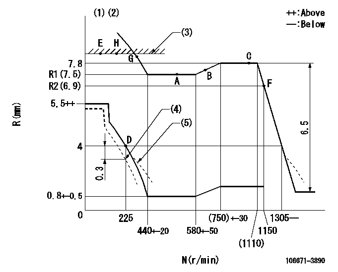
Injection quantity adjustment
Adjusting point
A
Rack position
R1(7.5)
Pump speed
r/min
500
500
500
Average injection quantity
mm3/st.
145
142
148
Max. variation between cylinders
%
0
-4
4
Fixing the lever
*
Injection quantity adjustment_02
Adjusting point
B
Rack position
7.7
Pump speed
r/min
700
700
700
Average injection quantity
mm3/st.
147
145
149
Max. variation between cylinders
%
0
-2
2
Basic
*
Fixing the lever
*
Injection quantity adjustment_03
Adjusting point
C
Rack position
7.8
Pump speed
r/min
1075
1075
1075
Average injection quantity
mm3/st.
151
145
157
Max. variation between cylinders
%
0
-4
4
Fixing the lever
*
Injection quantity adjustment_04
Adjusting point
D
Rack position
4+-0.5
Pump speed
r/min
225
225
225
Average injection quantity
mm3/st.
10
7
13
Max. variation between cylinders
%
0
-15
15
Fixing the rack
*
Injection quantity adjustment_05
Adjusting point
E
Rack position
9+-0.5
Pump speed
r/min
100
100
100
Average injection quantity
mm3/st.
158
153
163
Fixing the lever
*
Rack limit
*
Timer adjustment
Pump speed
r/min
(865)
Advance angle
deg.
0
0
0
Remarks
Start
Start
Timer adjustment_02
Pump speed
r/min
1075
Advance angle
deg.
4.5
4.2
4.8
Remarks
Finish
Finish
Test data Ex:
Governor adjustment
N:Pump speed
R:Rack position (mm)
(1)Lever ratio: RT
(2)Target shim dimension: TH
(3)RACK LIMIT: RAL
(4)Set to idle at shipping.
(5)Damper spring setting: DL
----------
RT=0.8 TH=2.7mm RAL=(9)mm DL=3.5-0.2mm
----------
----------
RT=0.8 TH=2.7mm RAL=(9)mm DL=3.5-0.2mm
----------
Speed control lever angle

F:Full speed
----------
----------
a=12deg+-5deg
----------
----------
a=12deg+-5deg
0000000901
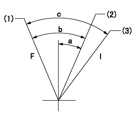
F:Full load
I:Idle
(1)Use the hole at R = aa
(2)Set point D
(3)At shipping
----------
aa=50mm
----------
a=16deg+-5deg b=36deg+-3deg c=37.5deg+-5deg
----------
aa=50mm
----------
a=16deg+-5deg b=36deg+-3deg c=37.5deg+-5deg
Stop lever angle
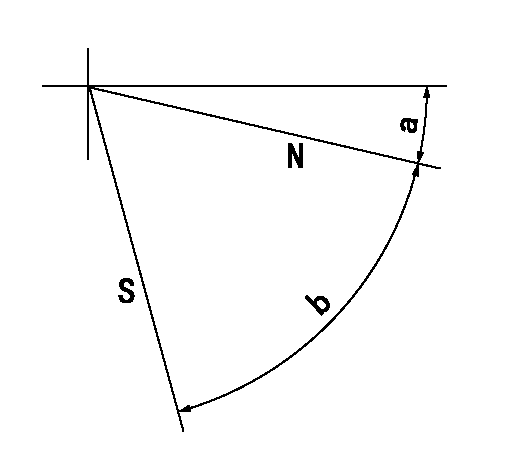
N:Pump normal
S:Stop the pump.
----------
----------
a=15deg+-5deg b=64deg+-5deg
----------
----------
a=15deg+-5deg b=64deg+-5deg
0000001501 RACK SENSOR
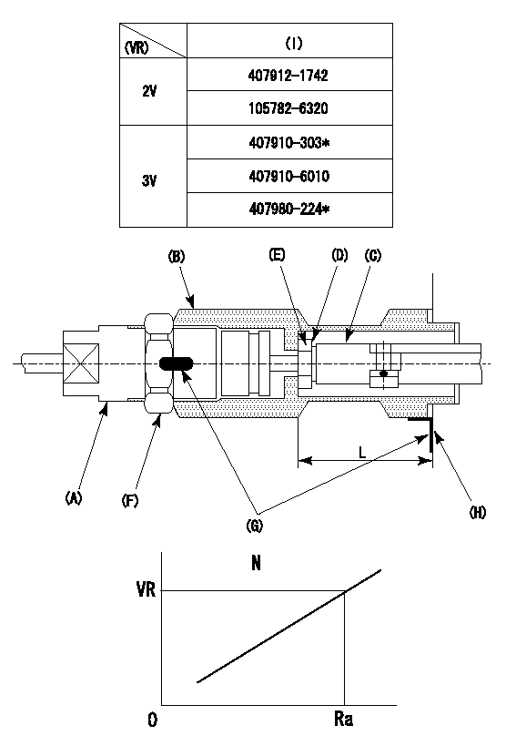
(VR) measurement voltage
(I) Part number of the control unit
(G) Apply red paint.
(H): End surface of the pump
1. Rack limit adjustment
(1)Mount the joint (B).
(2)Select the shim (D) so that the rack limit's rack position is obtained at that time.
(3)Install the rod (E) to the block (C).
The distance between the pump end face and the rod (E) at rack limit must be L.
2. Rack sensor adjustment (-0020)
(1)Screw in the bobbin (A) until it contacts the joint (B).
(2)Fix the speed control lever at the full side.
(3)Set at speed N.
(4)Adjust the depth that the bobbin (A) is screwed in so that the control unit's rack sensor output voltage is VR+-0.01 (V), then tighten the nut (F). (If equipped with a boost compensator, perform with boost pressure applied.)
(5)Adjust the bobbin (A) so that the rack sensor's output voltage is VR+-0.01.
(6)Apply G at two places.
Connecting part between the joint (B) and the nut (F)
Connecting part between the joint (B) and the end surface of the pump (H)
----------
L=38-0.2mm N=900r/min Ra=(7.8)mm
----------
----------
L=38-0.2mm N=900r/min Ra=(7.8)mm
----------
Timing setting
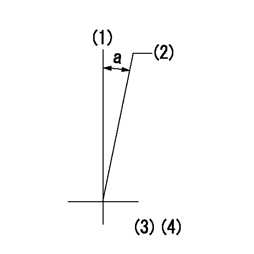
(1)Pump vertical direction
(2)Coupling's key groove position at No 1 cylinder's beginning of injection
(3)-
(4)-
----------
----------
a=(0deg)
----------
----------
a=(0deg)
Have questions with 106671-3890?
Group cross 106671-3890 ZEXEL
Hino
106671-3890
9 400 616 783
220004810A
INJECTION-PUMP ASSEMBLY
EK100
EK100