
Rating:
Information injection-pump assembly
BOSCH
9 400 610 044
9400610044
ZEXEL
106671-3793
1066713793
HINO
220201864B
220201864b
Service parts 106671-3793 INJECTION-PUMP ASSEMBLY:
1.
_
7.
COUPLING PLATE
8.
_
9.
_
11.
Nozzle and Holder
23600-1561C
12.
Open Pre:MPa(Kqf/cm2)
21.6{220}
15.
NOZZLE SET
Include in #1:
106671-3793
as INJECTION-PUMP ASSEMBLY
Cross reference number
BOSCH
9 400 610 044
9400610044
ZEXEL
106671-3793
1066713793
HINO
220201864B
220201864b
Zexel num
Bosch num
Firm num
Name
9 400 610 044
220201864B HINO
INJECTION-PUMP ASSEMBLY
EP100T K 14CA INJECTION PUMP ASSY PE6P,6PD PE
EP100T K 14CA INJECTION PUMP ASSY PE6P,6PD PE
Calibration Data:
Adjustment conditions
Test oil
1404 Test oil ISO4113 or {SAEJ967d}
1404 Test oil ISO4113 or {SAEJ967d}
Test oil temperature
degC
40
40
45
Nozzle and nozzle holder
105780-8140
Bosch type code
EF8511/9A
Nozzle
105780-0000
Bosch type code
DN12SD12T
Nozzle holder
105780-2080
Bosch type code
EF8511/9
Opening pressure
MPa
17.2
Opening pressure
kgf/cm2
175
Injection pipe
Outer diameter - inner diameter - length (mm) mm 8-3-600
Outer diameter - inner diameter - length (mm) mm 8-3-600
Overflow valve opening pressure
kPa
162
147
177
Overflow valve opening pressure
kgf/cm2
1.65
1.5
1.8
Tester oil delivery pressure
kPa
157
157
157
Tester oil delivery pressure
kgf/cm2
1.6
1.6
1.6
Direction of rotation (viewed from drive side)
Right R
Right R
Injection timing adjustment
Direction of rotation (viewed from drive side)
Right R
Right R
Injection order
1-4-2-6-
3-5
Pre-stroke
mm
4.5
4.4
4.5
Beginning of injection position
Drive side NO.1
Drive side NO.1
Difference between angles 1
Cal 1-4 deg. 60 59.5 60.5
Cal 1-4 deg. 60 59.5 60.5
Difference between angles 2
Cyl.1-2 deg. 120 119.5 120.5
Cyl.1-2 deg. 120 119.5 120.5
Difference between angles 3
Cal 1-6 deg. 180 179.5 180.5
Cal 1-6 deg. 180 179.5 180.5
Difference between angles 4
Cal 1-3 deg. 240 239.5 240.5
Cal 1-3 deg. 240 239.5 240.5
Difference between angles 5
Cal 1-5 deg. 300 299.5 300.5
Cal 1-5 deg. 300 299.5 300.5
Injection quantity adjustment
Adjusting point
A
Rack position
7.9
Pump speed
r/min
800
800
800
Average injection quantity
mm3/st.
111
109
113
Max. variation between cylinders
%
0
-2
2
Basic
*
Fixing the lever
*
Injection quantity adjustment_02
Adjusting point
B
Rack position
5.1+-0.5
Pump speed
r/min
360
360
360
Average injection quantity
mm3/st.
10
7
13
Max. variation between cylinders
%
0
-15
15
Fixing the rack
*
Injection quantity adjustment_03
Adjusting point
C
Rack position
-
Pump speed
r/min
100
100
100
Average injection quantity
mm3/st.
148.5
143.5
153.5
Fixing the lever
*
Rack limit
*
Timer adjustment
Pump speed
r/min
975--
Advance angle
deg.
0
0
0
Remarks
Start
Start
Timer adjustment_02
Pump speed
r/min
925
Advance angle
deg.
0.3
Timer adjustment_03
Pump speed
r/min
1000
Advance angle
deg.
0.8
0.3
1.3
Timer adjustment_04
Pump speed
r/min
-
Advance angle
deg.
2.5
2.5
2.5
Remarks
Measure the actual speed, stop
Measure the actual speed, stop
Test data Ex:
Governor adjustment
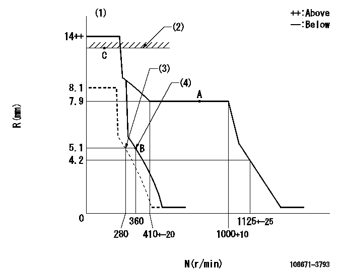
N:Pump speed
R:Rack position (mm)
(1)Target notch: K
(2)RACK LIMIT
(3)Set idle sub-spring
(4)Main spring setting
----------
K=(9)
----------
----------
K=(9)
----------
Speed control lever angle
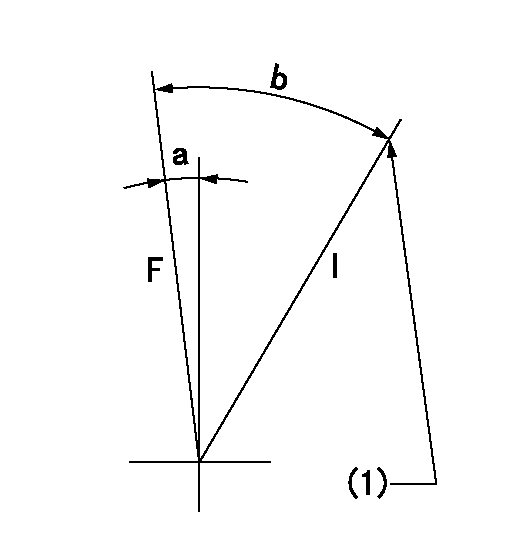
F:Full speed
I:Idle
(1)Stopper bolt setting
----------
----------
a=(2deg)+-5deg b=(17deg)+-5deg
----------
----------
a=(2deg)+-5deg b=(17deg)+-5deg
Stop lever angle
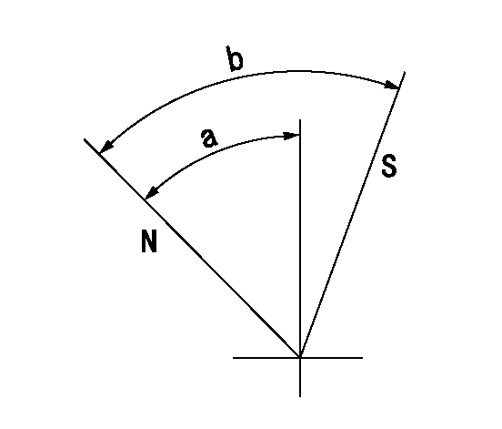
N:Pump normal
S:Stop the pump.
----------
----------
a=53deg+-3deg b=53deg+-5deg
----------
----------
a=53deg+-3deg b=53deg+-5deg
0000001501 Q ADJUSTMENT PIPING
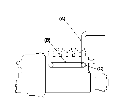
Tester fuel pipe A
Adjust screw A so that the timer advance angle determined in (B) can be obtained.
Fuel inlet C
Piping at standard injection quantity adjustment
1. Because the pump gallery is divided into two, be careful of the fuel piping at adjustment.
----------
----------
----------
----------
Timing setting
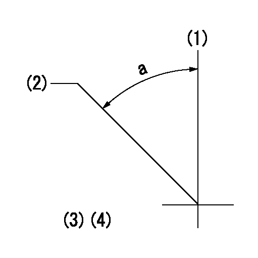
(1)Pump vertical direction
(2)Coupling's key groove position at No 1 cylinder's beginning of injection
(3)-
(4)-
----------
----------
a=(40deg)
----------
----------
a=(40deg)