
Rating:
Information injection-pump assembly
BOSCH
9 400 616 600
9400616600
ZEXEL
106661-2200
1066612200
MITSUBISHI
ME157824
me157824
Service parts 106661-2200 INJECTION-PUMP ASSEMBLY:
1.
_
7.
COUPLING PLATE
8.
_
9.
_
11.
Nozzle and Holder
12.
Open Pre:MPa(Kqf/cm2)
17.7(180)/24.5(250)

15.
NOZZLE SET
Include in #1:
106661-2200
as INJECTION-PUMP ASSEMBLY
Cross reference number
BOSCH
9 400 616 600
9400616600
ZEXEL
106661-2200
1066612200
MITSUBISHI
ME157824
me157824
Zexel num
Bosch num
Firm num
Name
106661-2200
9 400 616 600
ME157824 MITSUBISHI
INJECTION-PUMP ASSEMBLY
6D22-TL K
6D22-TL K
Calibration Data:
Adjustment conditions
Test oil
1404 Test oil ISO4113 or {SAEJ967d}
1404 Test oil ISO4113 or {SAEJ967d}
Test oil temperature
degC
40
40
45
Nozzle and nozzle holder
105780-8140
Bosch type code
EF8511/9A
Nozzle
105780-0000
Bosch type code
DN12SD12T
Nozzle holder
105780-2080
Bosch type code
EF8511/9
Opening pressure
MPa
17.2
Opening pressure
kgf/cm2
175
Injection pipe
Outer diameter - inner diameter - length (mm) mm 8-3-600
Outer diameter - inner diameter - length (mm) mm 8-3-600
Overflow valve
131424-6920
Overflow valve opening pressure
kPa
191
157
225
Overflow valve opening pressure
kgf/cm2
1.95
1.6
2.3
Tester oil delivery pressure
kPa
157
157
157
Tester oil delivery pressure
kgf/cm2
1.6
1.6
1.6
Direction of rotation (viewed from drive side)
Right R
Right R
Injection timing adjustment
Direction of rotation (viewed from drive side)
Right R
Right R
Injection order
1-5-3-6-
2-4
Pre-stroke
mm
4.8
4.75
4.85
Beginning of injection position
Governor side NO.1
Governor side NO.1
Difference between angles 1
Cal 1-5 deg. 60 59.5 60.5
Cal 1-5 deg. 60 59.5 60.5
Difference between angles 2
Cal 1-3 deg. 120 119.5 120.5
Cal 1-3 deg. 120 119.5 120.5
Difference between angles 3
Cal 1-6 deg. 180 179.5 180.5
Cal 1-6 deg. 180 179.5 180.5
Difference between angles 4
Cyl.1-2 deg. 240 239.5 240.5
Cyl.1-2 deg. 240 239.5 240.5
Difference between angles 5
Cal 1-4 deg. 300 299.5 300.5
Cal 1-4 deg. 300 299.5 300.5
Injection quantity adjustment
Adjusting point
A
Rack position
10.2
Pump speed
r/min
650
650
650
Average injection quantity
mm3/st.
138.5
136.5
140.5
Max. variation between cylinders
%
0
-2.5
2.5
Basic
*
Fixing the lever
*
Boost pressure
kPa
27.3
27.3
Boost pressure
mmHg
205
205
Injection quantity adjustment_02
Adjusting point
C
Rack position
6.5+-0.5
Pump speed
r/min
225
225
225
Average injection quantity
mm3/st.
17.5
14.9
20.1
Max. variation between cylinders
%
0
-15
15
Fixing the rack
*
Boost pressure
kPa
0
0
0
Boost pressure
mmHg
0
0
0
Injection quantity adjustment_03
Adjusting point
D
Rack position
8.6
Pump speed
r/min
700
700
700
Average injection quantity
mm3/st.
101.5
98.5
104.5
Fixing the lever
*
Boost pressure
kPa
0
0
0
Boost pressure
mmHg
0
0
0
Injection quantity adjustment_04
Adjusting point
E
Rack position
-
Pump speed
r/min
100
100
100
Average injection quantity
mm3/st.
135
115
155
Fixing the lever
*
Boost pressure
kPa
0
0
0
Boost pressure
mmHg
0
0
0
Boost compensator adjustment
Pump speed
r/min
700
700
700
Rack position
8.6
Boost pressure
kPa
5.3
5.3
5.3
Boost pressure
mmHg
40
40
40
Boost compensator adjustment_02
Pump speed
r/min
700
700
700
Rack position
10.2
Boost pressure
kPa
14
14
14
Boost pressure
mmHg
105
105
105
Timer adjustment
Pump speed
r/min
950--
Advance angle
deg.
0
0
0
Remarks
Start
Start
Timer adjustment_02
Pump speed
r/min
1100
Advance angle
deg.
4
3.5
4.5
Remarks
Finish
Finish
Test data Ex:
Governor adjustment
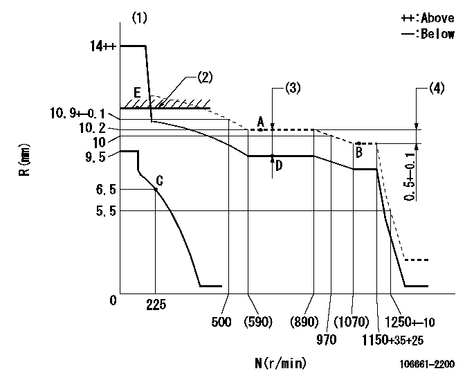
N:Pump speed
R:Rack position (mm)
(1)Target notch: K
(2)RACK LIMIT
(3)Boost compensator stroke: BCL
(4)Rack difference between N = N1 and N = N2
----------
K=14 BCL=1.6+-0.1mm N1=1100r/min N2=650r/min
----------
----------
K=14 BCL=1.6+-0.1mm N1=1100r/min N2=650r/min
----------
Speed control lever angle
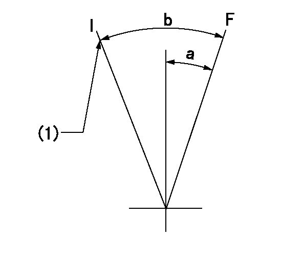
F:Full speed
I:Idle
(1)Stopper bolt setting
----------
----------
a=(12deg)+-5deg b=(28deg)+-5deg
----------
----------
a=(12deg)+-5deg b=(28deg)+-5deg
Stop lever angle
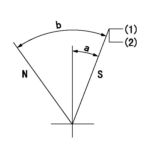
N:Pump normal
S:Stop the pump.
(1)Pump speed aa and rack position bb (to be sealed at delivery)
(2)Stopper bolt setting
----------
aa=0r/min bb=1-0.2mm
----------
a=35deg+-5deg b=70deg+-5deg
----------
aa=0r/min bb=1-0.2mm
----------
a=35deg+-5deg b=70deg+-5deg
Timing setting

(1)Pump vertical direction
(2)Coupling's key groove position at No 1 cylinder's beginning of injection
(3)B.T.D.C.: aa
(4)-
----------
aa=13deg
----------
a=(7deg)
----------
aa=13deg
----------
a=(7deg)
Have questions with 106661-2200?
Group cross 106661-2200 ZEXEL
Mitsubishi
106661-2200
9 400 616 600
ME157824
INJECTION-PUMP ASSEMBLY
6D22-TL
6D22-TL