
Rating:
Information injection-pump assembly
BOSCH
9 460 610 368
9460610368
ZEXEL
104769-2161
1047692161
Cross reference number
BOSCH
9 460 610 368
9460610368
ZEXEL
104769-2161
1047692161
Zexel num
Bosch num
Firm num
Name
104769-2161
9 460 610 368
INJECTION-PUMP ASSEMBLY
Calibration Data:
Adjustment conditions
Test oil
1404 Test oil ISO4113orSAEJ967d
1404 Test oil ISO4113orSAEJ967d
Test oil temperature
degC
45
45
50
Nozzle
105780-0060
Bosch type code
NP-DN0SD1510
Nozzle holder
105780-2150
Opening pressure
MPa
13
13
13.3
Opening pressure
kgf/cm2
133
133
136
Injection pipe
157805-7320
Injection pipe
Inside diameter - outside diameter - length (mm) mm 2-6-450
Inside diameter - outside diameter - length (mm) mm 2-6-450
Joint assembly
157641-4720
Tube assembly
157641-4020
Transfer pump pressure
kPa
20
20
20
Transfer pump pressure
kgf/cm2
0.2
0.2
0.2
Direction of rotation (viewed from drive side)
Right R
Right R
Injection timing adjustment
Pump speed
r/min
600
600
600
Boost pressure
kPa
0
0
0
Boost pressure
mmHg
0
0
0
Average injection quantity
mm3/st.
31.7
31.3
32.1
Difference in delivery
mm3/st.
2
Basic
*
Remarks
Full
Full
Injection timing adjustment_02
Pump speed
r/min
900
900
900
Boost pressure
kPa
33.35
32
34.7
Boost pressure
mmHg
250
240
260
Average injection quantity
mm3/st.
39
38.6
39.4
Difference in delivery
mm3/st.
2
Basic
*
Remarks
CBS
CBS
Injection timing adjustment_03
Pump speed
r/min
2500
2500
2500
Boost pressure
kPa
64
62.7
65.3
Boost pressure
mmHg
480
470
490
Average injection quantity
mm3/st.
19
14
24
Injection timing adjustment_04
Pump speed
r/min
2350
2350
2350
Boost pressure
kPa
64
62.7
65.3
Boost pressure
mmHg
480
470
490
Average injection quantity
mm3/st.
36.3
34.8
37.8
Injection timing adjustment_05
Pump speed
r/min
2300
2300
2300
Boost pressure
kPa
64
62.7
65.3
Boost pressure
mmHg
480
470
490
Average injection quantity
mm3/st.
41.3
37.8
44.8
Injection timing adjustment_06
Pump speed
r/min
2200
2200
2200
Boost pressure
kPa
64
62.7
65.3
Boost pressure
mmHg
480
470
490
Average injection quantity
mm3/st.
43.5
40.5
46.5
Injection timing adjustment_07
Pump speed
r/min
1800
1800
1800
Boost pressure
kPa
64
62.7
65.3
Boost pressure
mmHg
480
470
490
Average injection quantity
mm3/st.
43.2
41.2
45.2
Injection timing adjustment_08
Pump speed
r/min
1200
1200
1200
Boost pressure
kPa
64
62.7
65.3
Boost pressure
mmHg
480
470
490
Average injection quantity
mm3/st.
44
42
46
Injection timing adjustment_09
Pump speed
r/min
900
900
900
Boost pressure
kPa
33.35
32
34.7
Boost pressure
mmHg
250
240
260
Average injection quantity
mm3/st.
39
38.1
39.9
Remarks
Full
Full
Injection timing adjustment_10
Pump speed
r/min
600
600
600
Boost pressure
kPa
0
0
0
Boost pressure
mmHg
0
0
0
Average injection quantity
mm3/st.
31.7
30.8
32.6
Remarks
CBS
CBS
Injection quantity adjustment
Pump speed
r/min
2350
2350
2350
Boost pressure
kPa
64
62.7
65.3
Boost pressure
mmHg
480
470
490
Average injection quantity
mm3/st.
36.3
35.3
37.3
Difference in delivery
mm3/st.
4.5
Basic
*
Injection quantity adjustment_02
Pump speed
r/min
2800
2800
2800
Boost pressure
kPa
64
62.7
65.3
Boost pressure
mmHg
480
470
490
Average injection quantity
mm3/st.
3
Governor adjustment
Pump speed
r/min
350
350
350
Boost pressure
kPa
0
0
0
Boost pressure
mmHg
0
0
0
Average injection quantity
mm3/st.
7.6
6.6
8.6
Difference in delivery
mm3/st.
0.9
Basic
*
Governor adjustment_02
Pump speed
r/min
350
350
350
Boost pressure
kPa
0
0
0
Boost pressure
mmHg
0
0
0
Average injection quantity
mm3/st.
7.6
6.6
8.6
Governor adjustment_03
Pump speed
r/min
500
500
500
Boost pressure
kPa
0
0
0
Boost pressure
mmHg
0
0
0
Average injection quantity
mm3/st.
3
Boost compensator adjustment
Pump speed
r/min
900
900
900
Boost pressure
kPa
0
0
0
Boost pressure
mmHg
0
0
0
Average injection quantity
mm3/st.
9.6
6.6
12.6
Timer adjustment
Pump speed
r/min
100
100
100
Boost pressure
kPa
0
0
0
Boost pressure
mmHg
0
0
0
Average injection quantity
mm3/st.
38
38
Basic
*
Speed control lever angle
Pump speed
r/min
350
350
350
Boost pressure
kPa
0
0
0
Boost pressure
mmHg
0
0
0
Average injection quantity
mm3/st.
0
0
0
Remarks
Magnet OFF
Magnet OFF
Speed control lever angle_02
Pump speed
r/min
900
900
900
Boost pressure
kPa
46.95
45.6
48.3
Boost pressure
mmHg
352
342
362
Average injection quantity
mm3/st.
0
0
0
Remarks
Magnet OFF
Magnet OFF
0000000901
Pump speed
r/min
900
900
900
Boost pressure
kPa
46.8
45.6
48
Boost pressure
mmHg
352
342
362
Overflow quantity
cm3/min
390
258
522
Stop lever angle
Pump speed
r/min
900
900
900
Boost pressure
kPa
46.95
45.6
48.3
Boost pressure
mmHg
352
342
362
Pressure
kPa
372.5
343
402
Pressure
kgf/cm2
3.8
3.5
4.1
Basic
*
Stop lever angle_02
Pump speed
r/min
900
900
900
Boost pressure
kPa
46.95
45.6
48.3
Boost pressure
mmHg
352
342
362
Pressure
kPa
372.5
343
402
Pressure
kgf/cm2
3.8
3.5
4.1
Stop lever angle_03
Pump speed
r/min
1800
1800
1800
Boost pressure
kPa
46.95
45.6
48.3
Boost pressure
mmHg
352
342
362
Pressure
kPa
578.5
549
608
Pressure
kgf/cm2
5.9
5.6
6.2
Stop lever angle_04
Pump speed
r/min
2300
2300
2300
Boost pressure
kPa
46.95
45.6
48.3
Boost pressure
mmHg
352
342
362
Pressure
kPa
706
677
735
Pressure
kgf/cm2
7.2
6.9
7.5
0000001101
Pump speed
r/min
900
900
900
Boost pressure
kPa
46.95
45.6
48.3
Boost pressure
mmHg
352
342
362
Timer stroke
mm
1.3
1.1
1.5
Basic
*
_02
Pump speed
r/min
900
900
900
Boost pressure
kPa
46.95
45.6
48.3
Boost pressure
mmHg
352
342
362
Timer stroke
mm
1.3
1.1
1.5
_03
Pump speed
r/min
1800
1800
1800
Boost pressure
kPa
46.95
45.6
48.3
Boost pressure
mmHg
352
342
362
Timer stroke
mm
4.85
4.3
5.4
_04
Pump speed
r/min
2300
2300
2300
Boost pressure
kPa
46.95
45.6
48.3
Boost pressure
mmHg
352
342
362
Timer stroke
mm
6.85
6.3
7.4
_05
Pump speed
r/min
2500
2500
2500
Boost pressure
kPa
46.95
45.6
48.3
Boost pressure
mmHg
352
342
362
Timer stroke
mm
6.95
6.5
7.4
0000001201
Max. applied voltage
V
8
8
8
Test voltage
V
13
12
14
Timing setting
K dimension
mm
3.3
3.2
3.4
KF dimension
mm
6.64
6.54
6.74
MS dimension
mm
1.8
1.7
1.9
BCS stroke
mm
3.9
3.8
4
Control lever angle alpha
deg.
23
19
27
Control lever angle beta
deg.
42
37
47
Control lever angle gamma
deg.
11
10.5
11.5
Test data Ex:
0000001801 POTENTIOMETER ADJUSTMENT
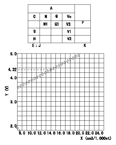
Adjustment of the potentiometer
Adjusting method (dummy bolt method):
1. Adjust at boost pressure P = P1 {P2}.
2. Position the control lever at the adjusting point in the table, hold the dummy bolt against the lever and then fix.
3. Install the potentiometer so that the output voltage is V3 (applied voltage Vi) at the fixed point.
4. After completing potentiometer installation, remove the dummy bolt.
In the following condition, change the installation position of the potentiometer to adjust the output voltage to within the specified values.
Measure the injection quantity at control lever position a (shim thickness = approximately L mm) at N = N1 r/min, determine the voltage using the formula, and adjust the potentiometer.
A:Adjustment conditions
B:Adjustment value
C:Position of the control lever
N:Pump speed
Q:Injection quantity
Vo:Output voltage
E:Conversion formula
F:Adjusting point
G:Idle
H:Full speed
K:Applied voltage
X:Injection quantity (cm3/1,000st)
Y:Voltage (V)
----------
P1=0kPa P2=0mmHg V3=4.32+-0.03V Vi=10V N1=1200r/min a=15.5deg L=8.4mm
----------
N1=1,200r/min V3=4.32+-0.03V Q1=14+-1cm3/1,000st V1=measure V2=measure K=10V J=V+-0.05=0.1115Q+2.7557
----------
P1=0kPa P2=0mmHg V3=4.32+-0.03V Vi=10V N1=1200r/min a=15.5deg L=8.4mm
----------
N1=1,200r/min V3=4.32+-0.03V Q1=14+-1cm3/1,000st V1=measure V2=measure K=10V J=V+-0.05=0.1115Q+2.7557
0000001901 M-CSD ADJUSTMENT
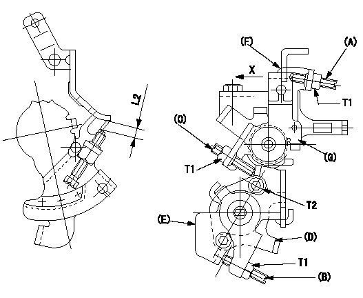
M-CSD adjustment
1. Move the lever E clockwise and when it contacts the stopper D, adjust screw B so that the timer piston advance is a (L1). Then, fix using the nut.
2. With intermediate lever screw (C)'s fixing lever (E) positioned as in 1., pull the intermediate lever in direction X. After confirming that it contacts the stop position, adjust so that screw (C) contacts lever (E) and then fix using the nut.
(In condition (2), intermediate lever: full speed position, at timer advance a.)
Confirm that the timer piston advances to b deg when the intermediate lever is returned.
3. Fast idle adjustment
Pull the intermediate lever in direction x to contact the stopper and adjust the screw (A) so that the gap between the idle set bracket and the idle screw is L2. Fix using the nut.
The gap between the control lever at the idle position and the screw (A) must be L3.
(F) Control lever
(G) Intermediate lever
----------
a=2deg b=0deg L1=1.6mm L2=6+-0.5mm L3=(1.7)mm
----------
T1=6~9N-m(0.6~0.9kgf-m) T2=5~7N-m(0.5~0.7kgf-m) L2=6+-0.5mm
----------
a=2deg b=0deg L1=1.6mm L2=6+-0.5mm L3=(1.7)mm
----------
T1=6~9N-m(0.6~0.9kgf-m) T2=5~7N-m(0.5~0.7kgf-m) L2=6+-0.5mm
0000002001 DASHPOT ADJUSTMENT
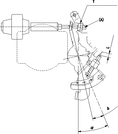
Adjustment of the dash pot
1. Insert a block gauge L (thickness gauge) between the idle set bracket and the idle screw.
2. In the above condition, adjust so that the dashpot adjusting screw (A) contacts the pushrod. Then, fix using the nut.
Record the dashpot return time t.
a = alpha
----------
L=3.8+-0.05mm t=1.8+-0.5sec
----------
T=6.0~7.0Nm{0.6~0.7kgfm} b=7.4deg L=3.8+-0.05mm
----------
L=3.8+-0.05mm t=1.8+-0.5sec
----------
T=6.0~7.0Nm{0.6~0.7kgfm} b=7.4deg L=3.8+-0.05mm
Have questions with 104769-2161?
Group cross 104769-2161 ZEXEL
104769-2161
9 460 610 368
INJECTION-PUMP ASSEMBLY