
Rating:
Information injection-pump assembly
BOSCH
F 01G 09W 0FR
f01g09w0fr
ZEXEL
104761-3020
1047613020
MITSUBISHI-HEAV
32B6500110
32b6500110
Compare Prices: .
As an associate, we earn commssions on qualifying purchases through the links below

Diesel Fuel Injection Pump 104661-3020 32B65-00110 VE6/11F1150RNP235 Compatible For Mitsubishi Truck
BsapP High-quality products with strong applicability. || Made of high quality materials, it is resistant to high temperature, wear and corrosion. || Plug and play, no splicing or cutting, easy installation and durability. || Precision work, high precision, stable performance, good quality, good decoration and long service life. || Diesel Fuel Injection Pump 104661-3020 32B65-00110 VE6/11F1150RNP235 Compatible For Mitsubishi Truck
BsapP High-quality products with strong applicability. || Made of high quality materials, it is resistant to high temperature, wear and corrosion. || Plug and play, no splicing or cutting, easy installation and durability. || Precision work, high precision, stable performance, good quality, good decoration and long service life. || Diesel Fuel Injection Pump 104661-3020 32B65-00110 VE6/11F1150RNP235 Compatible For Mitsubishi Truck

Diesel Fuel Injection Pump 104661-3020 32B65-00110 VE6/11F1150RNP235 Compatible With Mitsubishi Truck
TUMALO The output fuel pressure of the fuel injection pump is usually between 1000 and 2000 psi (about 6.9 to 13.8 MPa). || The plunger is one of the core components in the fuel injection pump, which generates a high pressure fuel pulse by moving up and down. || The drive gear is the power source of the fuel injection pump, usually driven by the crankshaft. || The pressure regulator is used to adjust the pressure of the fuel injection pump output to adapt to different engine loads and working conditions. || The control valve is one of the key components in the fuel injection pump, which determines the timing and amount of fuel injection according to the control signal.
TUMALO The output fuel pressure of the fuel injection pump is usually between 1000 and 2000 psi (about 6.9 to 13.8 MPa). || The plunger is one of the core components in the fuel injection pump, which generates a high pressure fuel pulse by moving up and down. || The drive gear is the power source of the fuel injection pump, usually driven by the crankshaft. || The pressure regulator is used to adjust the pressure of the fuel injection pump output to adapt to different engine loads and working conditions. || The control valve is one of the key components in the fuel injection pump, which determines the timing and amount of fuel injection according to the control signal.

Diesel Fuel Injection Pump 104661-3020 32B65-00110 VE6/11F1150RNP235,Compatible For Mitsubishi Truck
AKkis ♥ Diesel Fuel Injection Pump 104661-3020 32B65-00110 VE6/11F1150RNP235,Compatible For Mitsubishi Truck || ♥ Adaptability: Fuel pumps are widely adaptable and can adapt to different types of engines and fuel systems to meet the needs of various vehicles and provide better performance and driving experience. || ♥ High-pressure drive: The fuel pump can provide sufficient fuel pressure to ensure that the fuel can be delivered smoothly to all parts of the engine, keep it in normal working condition, and improve the operating efficiency and power output of the engine. || ♥ Safety: The fuel pump is equipped with a variety of safety devices and protection mechanisms, such as over-pressure protection, over-current protection, etc., to ensure that the fuel supply is cut off in time under abnormal conditions and to protect the safety of vehicles and passengers. || ♥ Durability: Using high-quality materials and strict manufacturing processes, it has a long service life, can withstand harsh environmental and working conditions, reduce the frequency of failure and maintenance, improve the reliability of the vehicle, and reduce maintenance costs.
AKkis ♥ Diesel Fuel Injection Pump 104661-3020 32B65-00110 VE6/11F1150RNP235,Compatible For Mitsubishi Truck || ♥ Adaptability: Fuel pumps are widely adaptable and can adapt to different types of engines and fuel systems to meet the needs of various vehicles and provide better performance and driving experience. || ♥ High-pressure drive: The fuel pump can provide sufficient fuel pressure to ensure that the fuel can be delivered smoothly to all parts of the engine, keep it in normal working condition, and improve the operating efficiency and power output of the engine. || ♥ Safety: The fuel pump is equipped with a variety of safety devices and protection mechanisms, such as over-pressure protection, over-current protection, etc., to ensure that the fuel supply is cut off in time under abnormal conditions and to protect the safety of vehicles and passengers. || ♥ Durability: Using high-quality materials and strict manufacturing processes, it has a long service life, can withstand harsh environmental and working conditions, reduce the frequency of failure and maintenance, improve the reliability of the vehicle, and reduce maintenance costs.
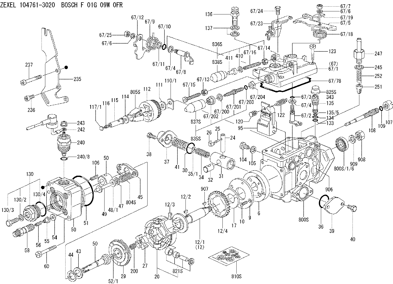
Components :
| 0. | INJECTION-PUMP ASSEMBLY | 104761-3020 |
| 1. | _ | |
| 2. | FUEL INJECTION PUMP | |
| 3. | NUMBER PLATE | 146940-1500 |
| 4. | _ | |
| 5. | CAPSULE | |
| 6. | ADJUSTING DEVICE | |
| 7. | NOZZLE AND HOLDER ASSY | |
| 8. | Nozzle and Holder | |
| 9. | Open Pre:MPa(Kqf/cm2) | |
| 10. | NOZZLE-HOLDER | |
| 11. | NOZZLE |
Scheme ###:
| 1/6. | [1] | 146601-0900 | PACKING RING |
| 6. | [1] | 146100-0420 | SUPPLY PUMP |
| 9. | [1] | 146103-0100 | COVER |
| 10. | [2] | 139104-0000 | FLAT-HEAD SCREW |
| 12. | [1] | 146200-0020 | DRIVE SHAFT |
| 12/1. | [1] | 146200-0000 | DRIVE SHAFT |
| 12/2. | [1] | 146201-0000 | WOODRUFF KEY |
| 12/3. | [2] | 146202-0100 | DAMPER |
| 12/4. | [1] | 146203-0000 | TOOTHED GEAR |
| 17. | [1] | 146204-0000 | PLAIN WASHER |
| 20. | [1] | 146210-2720 | ROLLER SET |
| 24. | [1] | 146303-0000 | BEARING PIN |
| 25. | [1] | 146304-0000 | BEARING PIN |
| 26. | [1] | 146305-0000 | CLAMPING BAND |
| 27. | [1] | 146205-0000 | SLOTTED WASHER |
| 29. | [1] | 146221-1920 | CAM PLATE |
| 30. | [1] | 146600-0800 | O-RING |
| 31. | [1] | 146311-8820 | PUMP PLUNGER |
| 32. | [1] | 146301-0000 | SLIDING PIECE |
| 34. | [1] | 146312-6100 | COMPRESSION SPRING |
| 34B. | [1] | 146312-6500 | COMPRESSION SPRING |
| 34C. | [1] | 146312-2200 | COMPRESSION SPRING |
| 35/1. | [1] | 146690-3200 | SHIM D11.5&9.4T0.1 |
| 35/1. | [1] | 146690-3300 | SHIM D11.5&9.4T0.2 |
| 35/1. | [1] | 146690-3400 | SHIM D11.5&9.4T0.25 |
| 35/1. | [1] | 146690-3500 | SHIM D11.5&9.4T1.0 |
| 35/1. | [1] | 146690-4100 | SHIM D11.5&9.4T2 |
| 35/1. | [1] | 146690-4200 | SHIM D11.5&9.4T0.5 |
| 35/1. | [1] | 146690-4300 | SHIM D11.5&9.4T0.75 |
| 36. | [1] | 146600-0800 | O-RING |
| 37. | [1] | 146310-4020 | COVER |
| 38. | [2] | 146620-5000 | BLEEDER SCREW |
| 39. | [1] | 146310-0100 | COVER |
| 40. | [2] | 146620-5000 | BLEEDER SCREW |
| 41. | [1] | 146312-1900 | COMPRESSION SPRING |
| 43. | [1] | 146230-0000 | SHIM |
| 44. | [1] | 146230-0100 | PLAIN WASHER |
| 45. | [1] | 146231-0001 | SLOTTED WASHER |
| 47. | [2] | 146233-0000 | SLOTTED WASHER |
| 48/1. | [1] | 146603-0000 | SHIM D17.0&5.2T0.50 |
| 48/1. | [1] | 146603-0100 | SHIM D17.0&5.2T0.80 |
| 48/1. | [1] | 146603-0200 | SHIM D17.0&5.2T1.00 |
| 48/1. | [1] | 146603-0300 | SHIM D17.0&5.2T1.20 |
| 48/1. | [1] | 146603-0400 | SHIM D17.0&5.2T1.50 |
| 48/1. | [1] | 146603-0500 | SHIM D17.0&5.2T1.80 |
| 48/1. | [1] | 146603-0600 | SHIM D17.0&5.2T2.00 |
| 48/1. | [1] | 146690-1400 | SHIM D17&5.2T0.9 |
| 48/1. | [1] | 146690-1500 | SHIM D17&5.2T1.1 |
| 48/1. | [1] | 146690-1600 | SHIM D17&5.2T1.3 |
| 48/1. | [1] | 146690-1700 | SHIM D17&5.2T1.4 |
| 48/1. | [1] | 146690-1800 | SHIM D17&5.2T1.6 |
| 48/1. | [1] | 146690-1900 | SHIM D17&5.2T1.7 |
| 48/1. | [1] | 146690-5800 | SHIM D17&5.2T2.1 |
| 48/1. | [1] | 146690-5900 | SHIM D17&5.2T2.2 |
| 48/1. | [1] | 146690-6000 | SHIM D17&5.2T2.3 |
| 48/1. | [1] | 146690-6100 | SHIM D17&5.2T2.4 |
| 48/1. | [1] | 146690-6200 | SHIM D17&5.2T2.5 |
| 48/1. | [1] | 146690-6300 | SHIM D17&5.2T2.6 |
| 48/1. | [1] | 146690-6400 | SHIM D17&5.2T2.7 |
| 48/1. | [1] | 146690-6500 | SHIM D17&5.2T2.8 |
| 48/1. | [1] | 146690-6600 | SHIM D17&5.2T2.9 |
| 48/1. | [1] | 146690-6700 | SHIM D17&5.2T3.0 |
| 48/1. | [1] | 146690-6800 | SHIM D17&5.2T3.1 |
| 48/1. | [1] | 146690-6900 | SHIM D17&5.2T3.2 |
| 48/1. | [1] | 146690-7000 | SHIM D17&5.2T3.3 |
| 48/1. | [1] | 146690-7100 | SHIM D17&5.2T3.4 |
| 48/1. | [1] | 146690-7200 | SHIM D17&5.2T0.4 |
| 48/1. | [1] | 146690-7300 | SHIM D17&5.2T0.6 |
| 48/1. | [1] | 146690-7400 | SHIM D17&5.2T0.7 |
| 48/1. | [1] | 146690-7500 | SHIM D17&5.2T1.9 |
| 48/1. | [1] | 146690-7800 | SHIM D17&5.2T0.2 |
| 49. | [2] | 146234-0600 | GUIDE PIN |
| 50. | [1] | 146405-4420 | HYDRAULIC HEAD |
| 50. | [1] | 146405-4420 | HYDRAULIC HEAD |
| 50. | [1] | 146405-4420 | HYDRAULIC HEAD |
| 51. | [1] | 146600-0000 | O-RING |
| 52/1. | [1] | 146420-0000 | SHIM D9.5&3.0T1.90 |
| 52/1. | [1] | 146420-0100 | SHIM D9.5&3.0T1.92 |
| 52/1. | [1] | 146420-0200 | SHIM D9.5&3.0T1.94 |
| 52/1. | [1] | 146420-0300 | SHIM D9.5&3.0T1.96 |
| 52/1. | [1] | 146420-0400 | SHIM D9.5&3.0T1.98 |
| 52/1. | [1] | 146420-0500 | SHIM D9.5&3.0T2.00 |
| 52/1. | [1] | 146420-0600 | SHIM D9.5&3.0T2.02 |
| 52/1. | [1] | 146420-0700 | SHIM D9.5&3.0T2.04 |
| 52/1. | [1] | 146420-0800 | SHIM D9.5&3.0T2.06 |
| 52/1. | [1] | 146420-0900 | SHIM D9.5&3.0T2.08 |
| 52/1. | [1] | 146420-1000 | SHIM D9.5&3.0T2.10 |
| 52/1. | [1] | 146420-1100 | SHIM D9.5&3.0T2.12 |
| 52/1. | [1] | 146420-1200 | SHIM D9.5&3.0T2.14 |
| 52/1. | [1] | 146420-1300 | SHIM D9.5&3.0T2.16 |
| 52/1. | [1] | 146420-1400 | SHIM D9.5&3.0T2.18 |
| 52/1. | [1] | 146420-1500 | SHIM D9.5&3.0T2.20 |
| 52/1. | [1] | 146420-1600 | SHIM D9.5&3.0T2.22 |
| 52/1. | [1] | 146420-1700 | SHIM D9.5&3.0T2.24 |
| 52/1. | [1] | 146420-1800 | SHIM D9.5&3.0T2.26 |
| 52/1. | [1] | 146420-1900 | SHIM D9.5&3.0T2.28 |
| 52/1. | [1] | 146420-2000 | SHIM D9.5&3.0T2.30 |
| 52/1. | [1] | 146420-2100 | SHIM D9.5&3.0T2.32 |
| 52/1. | [1] | 146420-2200 | SHIM D9.5&3.0T2.34 |
| 52/1. | [1] | 146420-2300 | SHIM D9.5&3.0T2.36 |
| 52/1. | [1] | 146420-2400 | SHIM D9.5&3.0T2.38 |
| 52/1. | [1] | 146420-2500 | SHIM D9.5&3.0T2.40 |
| 52/1. | [1] | 146420-2600 | SHIM D9.5&3.0T2.42 |
| 52/1. | [1] | 146420-2700 | SHIM D9.5&3.0T2.44 |
| 52/1. | [1] | 146420-2800 | SHIM D9.5&3.0T2.46 |
| 52/1. | [1] | 146420-2900 | SHIM D9.5&3.0T2.48 |
| 52/1. | [1] | 146420-3000 | SHIM D9.5&3.0T2.50 |
| 52/1. | [1] | 146420-3100 | SHIM D9.5&3.0T2.52 |
| 52/1. | [1] | 146420-3200 | SHIM D9.5&3.0T2.54 |
| 52/1. | [1] | 146420-3300 | SHIM D9.5&3.0T2.56 |
| 52/1. | [1] | 146420-3400 | SHIM D9.5&3.0T2.58 |
| 52/1. | [1] | 146420-3500 | SHIM D9.5&3.0T2.60 |
| 52/1. | [1] | 146420-3600 | SHIM D9.5&3.0T2.62 |
| 52/1. | [1] | 146420-3700 | SHIM D9.5&3.0T2.64 |
| 52/1. | [1] | 146420-3800 | SHIM D9.5&3.0T2.66 |
| 52/1. | [1] | 146420-3900 | SHIM D9.5&3.0T2.68 |
| 52/1. | [1] | 146420-4000 | SHIM D9.5&3.0T2.70 |
| 52/1. | [1] | 146420-4100 | SHIM D9.5&3.0T2.72 |
| 52/1. | [1] | 146420-4200 | SHIM D9.5&3.0T2.74 |
| 52/1. | [1] | 146420-4300 | SHIM D9.5&3.0T2.76 |
| 52/1. | [1] | 146420-4400 | SHIM D9.5&3.0T2.78 |
| 52/1. | [1] | 146420-4500 | SHIM D9.5&3.0T2.80 |
| 52/1. | [1] | 146420-4600 | SHIM D9.5&3.0T2.82 |
| 52/1. | [1] | 146420-4700 | SHIM D9.5&3.0T2.84 |
| 52/1. | [1] | 146420-4800 | SHIM D9.5&3.0T2.86 |
| 52/1. | [1] | 146420-4900 | SHIM D9.5&3.0T2.88 |
| 52/1. | [1] | 146420-5000 | SHIM D9.5&3.0T2.90 |
| 52/1. | [1] | 146420-5100 | SHIM D9.5&3.0T1.74 |
| 52/1. | [1] | 146420-5200 | SHIM D9.5&3.0T1.76 |
| 52/1. | [1] | 146420-5300 | SHIM D9.5&3.0T1.78 |
| 52/1. | [1] | 146420-5400 | SHIM D9.5&3.0T1.80 |
| 52/1. | [1] | 146420-5500 | SHIM D9.5&3.0T1.82 |
| 52/1. | [1] | 146420-5600 | SHIM D9.5&3.0T1.84 |
| 52/1. | [1] | 146420-5700 | SHIM D9.5&3.0T1.86 |
| 52/1. | [1] | 146420-5800 | SHIM D9.5&3.0T1.88 |
| 54. | [6] | 146433-0100 | GASKET |
| 55. | [6] | 146430-3320 | DELIVERY-VALVE ASSEMBLY VE33 |
| 56. | [6] | 146432-0000 | COMPRESSION SPRING |
| 58. | [6] | 146440-0220 | FITTING |
| 60. | [3] | 139106-0100 | FLAT-HEAD SCREW |
| 67. | [1] | 146822-1220 | GOVERNOR COVER |
| 67/1. | [1] | 146508-1022 | GOVERNOR COVER |
| 67/2. | [1] | 146515-0320 | CONTROL SHAFT |
| 67/3. | [1] | 146600-0100 | O-RING |
| 67/4. | [2] | 139310-0200 | PLAIN WASHER |
| 67/4. | [2] | 139310-0200 | PLAIN WASHER |
| 67/5. | [1] | 146832-5500 | CONTROL LEVER MARK:255 |
| 67/5B. | [1] | 146832-5600 | CONTROL LEVER MARK:256 |
| 67/5C. | [1] | 146832-9300 | CONTROL LEVER MARK:293 |
| 67/5D. | [1] | 146832-9400 | CONTROL LEVER MARK:294 |
| 67/6. | [2] | 014110-6440 | LOCKING WASHER D12.2&6.1T1.5 |
| 67/6. | [2] | 014110-6440 | LOCKING WASHER D12.2&6.1T1.5 |
| 67/7. | [1] | 013020-6040 | UNION NUT |
| 67/8. | [1] | 146515-1820 | LEVER SHAFT |
| 67/9. | [1] | 146587-4500 | COILED SPRING |
| 67/10. | [1] | 146600-0200 | O-RING |
| 67/11. | [1] | 146602-0100 | PLAIN WASHER |
| 67/12. | [1] | 146540-1300 | CONTROL LEVER |
| 67/12B. | [1] | 146540-1400 | CONTROL LEVER MARK:0 |
| 67/12C. | [1] | 146540-5200 | CONTROL LEVER |
| 67/12D. | [1] | 146540-5300 | CONTROL LEVER |
| 67/13. | [1] | 146621-1700 | UNION NUT |
| 67/14. | [1] | 146621-1700 | UNION NUT |
| 67/15. | [1] | 146526-3400 | BLEEDER SCREW |
| 67/16. | [1] | 146526-7300 | FLAT-HEAD SCREW |
| 67/18. | [1] | 146587-0400 | COILED SPRING |
| 67/19. | [1] | 146541-0000 | ANGLE PIECE |
| 67/23. | [1] | 146925-2520 | BRACKET |
| 67/24. | [2] | 139006-4500 | BLEEDER SCREW |
| 67/25. | [1] | 013020-6040 | UNION NUT |
| 67/78. | [1] | 146600-4400 | SEAL RING |
| 67/200. | [1] | 139308-0300 | PLAIN WASHER |
| 67/201. | [1] | 146545-4600 | THREADED PIN L=24MM |
| 67/201B. | [1] | 146545-4700 | THREADED PIN L=26MM |
| 67/201C. | [1] | 146545-4800 | THREADED PIN L=28MM |
| 67/202. | [1] | 146598-5000 | UNION NUT |
| 67/203. | [1] | 146600-1200 | O-RING |
| 67/204. | [1] | 146545-4500 | DAMPER |
| 95. | [1] | 146855-2020 | FULCRUM LEVER |
| 104. | [2] | 146568-0000 | SLOTTED SPRING PIN |
| 105. | [2] | 026508-1140 | GASKET D11.4&8.2T1.0 |
| 106. | [2] | 146588-0500 | COILED SPRING |
| 107. | [1] | 146569-0300 | UNION NUT |
| 108. | [1] | 146570-0420 | GOVERNOR SHAFT |
| 109. | [1] | 146600-0400 | O-RING |
| 110/1. | [1] | 146571-0000 | SHIM D20.2&8.3T1.05 |
| 110/1. | [1] | 146571-0100 | SHIM D20.2&8.3T1.25 |
| 110/1. | [1] | 146571-0200 | SHIM D20.2&8.3T1.45 |
| 110/1. | [1] | 146571-0300 | SHIM D20.2&8.3T1.65 |
| 110/1. | [1] | 146571-0400 | SHIM D20.2&8.3T1.85 |
| 110/1. | [1] | 146571-0500 | SHIM D20.2&8.3T1.15 |
| 110/1. | [1] | 146571-0600 | SHIM D20.2&8.3T1.35 |
| 110/1. | [1] | 146571-0700 | SHIM D20.2&8.3T1.55 |
| 110/1. | [1] | 146571-0800 | SHIM D20.2&8.3T1.75 |
| 111. | [1] | 146602-0600 | PLAIN WASHER |
| 112. | [1] | 146572-0020 | FLYWEIGHT ASSEMBLY |
| 114. | [1] | 146602-2600 | PLAIN WASHER |
| 115. | [1] | 146976-1200 | SLIDING SLEEVE |
| 116. | [1] | 146576-0200 | CAP |
| 117/1. | [1] | 146577-1800 | PLUG L2.10 |
| 117/1. | [1] | 146577-1900 | PLUG L2.30 |
| 117/1. | [1] | 146577-2000 | PLUG L2.50 |
| 117/1. | [1] | 146577-2100 | PLUG L2.70 |
| 117/1. | [1] | 146577-2200 | PLUG L2.90 |
| 117/1. | [1] | 146577-2300 | PLUG L3.10 |
| 117/1. | [1] | 146577-2400 | PLUG L3.30 |
| 117/1. | [1] | 146577-2500 | PLUG L3.50 |
| 117/1. | [1] | 146577-2600 | PLUG L3.70 |
| 117/1. | [1] | 146577-2700 | PLUG L3.90 |
| 117/1. | [1] | 146577-2800 | PLUG L4.10 |
| 117/1. | [1] | 146577-2900 | PLUG L4.30 |
| 117/1. | [1] | 146577-3000 | PLUG L4.50 |
| 117/1. | [1] | 146577-3100 | PLUG L4.70 |
| 117/1. | [1] | 146577-3200 | PLUG L4.90 |
| 117/1. | [1] | 146577-3300 | PLUG L5.10 |
| 117/1. | [1] | 146577-6700 | PLUG L2.2 |
| 117/1. | [1] | 146577-6800 | PLUG L2.4 |
| 117/1. | [1] | 146577-6900 | PLUG L2.6 |
| 117/1. | [1] | 146577-7000 | PLUG L2.8 |
| 117/1. | [1] | 146577-7100 | PLUG L3.0 |
| 117/1. | [1] | 146577-7200 | PLUG L3.2 |
| 117/1. | [1] | 146577-7300 | PLUG L3.4 |
| 117/1. | [1] | 146577-7400 | PLUG L3.6 |
| 117/1. | [1] | 146577-7500 | PLUG L3.8 |
| 117/1. | [1] | 146577-7600 | PLUG L4.0 |
| 117/1. | [1] | 146577-7700 | PLUG L4.2 |
| 117/1. | [1] | 146577-7800 | PLUG L4.4 |
| 117/1. | [1] | 146577-7900 | PLUG L4.6 |
| 117/1. | [1] | 146577-8000 | PLUG L4.8 |
| 117/1. | [1] | 146577-8100 | PLUG L5.0 |
| 117/1. | [1] | 146877-0000 | PLUG L5.2 |
| 117/1. | [1] | 146877-0100 | PLUG L5.3 |
| 117/1. | [1] | 146877-0200 | PLUG L5.4 |
| 117/1. | [1] | 146877-0300 | PLUG L5.5 |
| 117/1. | [1] | 146877-4700 | PLUG L5.6 |
| 117/1. | [1] | 146877-4800 | PLUG L5.7 |
| 117/1. | [1] | 146877-4900 | PLUG L5.8 |
| 117/1. | [1] | 146877-5000 | PLUG L5.9 |
| 120. | [1] | 146879-3720 | RETAINING PIN |
| 122. | [1] | 146580-1400 | GOVERNOR SPRING |
| 123. | [4] | 139106-0200 | FLAT-HEAD SCREW |
| 130. | [1] | 146421-0020 | CAPSULE |
| 130/2. | [1] | 026508-1140 | GASKET D11.4&8.2T1.0 |
| 130/3. | [1] | 146422-0000 | BLEEDER SCREW |
| 130/4. | [1] | 146600-0500 | O-RING |
| 133. | [1] | 146600-0600 | O-RING |
| 134. | [1] | 146600-0700 | O-RING |
| 135. | [1] | 146110-3720 | CONTROL VALVE |
| 135/5. | [1] | 146114-0000 | SPRING WASHER |
| 136. | [1] | 146120-0120 | OVER FLOW VALVE |
| 137. | [2] | 139512-0500 | GASKET |
| 200. | [1] | 146206-0100 | COILED SPRING |
| 235. | [1] | 146936-3000 | BRACKET |
| 236. | [2] | 010206-2240 | HEX-SOCKET-HEAD CAP SCREW |
| 237. | [1] | 146620-0200 | HEX-SOCKET-HEAD CAP SCREW |
| 240. | [1] | 146650-0820 | PULLING ELECTROMAGNET |
| 240/8. | [1] | 146600-1700 | O-RING |
| 242. | [1] | 146662-0120 | WIRE |
| 243. | [1] | 146621-4901 | UNION NUT |
| 245. | [1] | 139512-0500 | GASKET |
| 247. | [1] | 146669-1720 | INLET UNION |
| 251. | [1] | 146125-0101 | FILTER |
| 252. | [1] | 146125-0200 | COILED SPRING |
| 343. | [1] | 146598-8700 | CAP NUT |
| 410. | [1] | 014020-6140 | PLAIN WASHER D11.5&6.5 |
| 411. | [1] | 146598-6300 | CAP NUT |
| 800S. | [1] | 146020-1820 | PUMP HOUSING |
| 800S/1/6. | [1] | 146601-0900 | PACKING RING |
| 804S. | [1] | 146232-0720 | COMPRESSION SPRING |
| 805S. | [1] | 146574-0320 | PARTS SET |
| 810S. | [1] | 146600-1120 | REPAIR SET |
| 821S. | [1] | 146210-5720 | ROLLER SET |
| 825S. | [1] | 146598-8600 | CAP NUT |
| 835S. | [1] | 146598-7320 | CAP |
| 836S. | [1] | 146598-7920 | CAP |
| 837S. | [1] | 146598-7310 | CAP |
| 838S. | [1] | 146598-6710 | CAP |
| 906. | [1] | 146940-1500 | NAMEPLATE |
| 907. | [1] | 025803-1640 | WOODRUFF KEY |
| 908. | [1] | 013021-2140 | UNION NUT |
| 909. | [1] | 014111-2440 | LOCKING WASHER |
Include in #2:
104761-3020
as INJECTION-PUMP ASSEMBLY
Cross reference number
BOSCH
F 01G 09W 0FR
f01g09w0fr
ZEXEL
104761-3020
1047613020
MITSUBISHI-HEAV
32B6500110
32b6500110
Zexel num
Bosch num
Firm num
Name
Calibration Data:
Adjustment conditions
Test oil
1404 Test oil ISO4113orSAEJ967d
1404 Test oil ISO4113orSAEJ967d
Test oil temperature
degC
45
45
50
Nozzle
105780-0060
Bosch type code
NP-DN0SD1510
Nozzle holder
105780-2150
Opening pressure
MPa
13
13
13.3
Opening pressure
kgf/cm2
133
133
136
Injection pipe
157805-7320
Injection pipe
Inside diameter - outside diameter - length (mm) mm 2-6-450
Inside diameter - outside diameter - length (mm) mm 2-6-450
Joint assembly
157641-4720
Tube assembly
157641-4020
Transfer pump pressure
kPa
20
20
20
Transfer pump pressure
kgf/cm2
0.2
0.2
0.2
Direction of rotation (viewed from drive side)
Right R
Right R
Injection timing adjustment
Pump speed
r/min
850
850
850
Average injection quantity
mm3/st.
49.9
49.4
50.4
Difference in delivery
mm3/st.
4.5
Basic
*
Oil temperature
degC
50
48
52
Injection timing adjustment_02
Pump speed
r/min
500
500
500
Average injection quantity
mm3/st.
48.6
44.1
53.1
Oil temperature
degC
48
46
50
Injection timing adjustment_03
Pump speed
r/min
850
850
850
Average injection quantity
mm3/st.
49.9
48.9
50.9
Difference in delivery
mm3/st.
5
Basic
*
Oil temperature
degC
50
48
52
Injection timing adjustment_04
Pump speed
r/min
1150
1150
1150
Average injection quantity
mm3/st.
48.2
43.2
53.2
Oil temperature
degC
50
48
52
Injection quantity adjustment
Pump speed
r/min
1285
1285
1285
Average injection quantity
mm3/st.
9.3
7.3
11.3
Difference in delivery
mm3/st.
3
Basic
*
Oil temperature
degC
50
48
52
Injection quantity adjustment_02
Pump speed
r/min
1400
1400
1400
Average injection quantity
mm3/st.
3
Oil temperature
degC
50
48
52
Injection quantity adjustment_03
Pump speed
r/min
1285
1285
1285
Average injection quantity
mm3/st.
9.3
6.8
11.8
Difference in delivery
mm3/st.
3.5
Basic
*
Oil temperature
degC
50
48
52
Governor adjustment
Pump speed
r/min
410
410
410
Average injection quantity
mm3/st.
11.3
9.3
13.3
Difference in delivery
mm3/st.
3
Basic
*
Oil temperature
degC
48
46
50
Governor adjustment_02
Pump speed
r/min
410
410
410
Average injection quantity
mm3/st.
11.3
8.8
13.8
Difference in delivery
mm3/st.
3.5
Basic
*
Oil temperature
degC
48
46
50
Timer adjustment
Pump speed
r/min
100
100
100
Average injection quantity
mm3/st.
55.7
50.7
60.7
Basic
*
Oil temperature
degC
48
46
50
Remarks
Full
Full
Timer adjustment_02
Pump speed
r/min
100
100
100
Average injection quantity
mm3/st.
55.7
50.7
60.7
Oil temperature
degC
48
46
50
Remarks
Full
Full
Speed control lever angle
Pump speed
r/min
410
410
410
Average injection quantity
mm3/st.
0
0
0
Oil temperature
degC
48
46
50
Remarks
Magnet OFF at idling position
Magnet OFF at idling position
0000000901
Pump speed
r/min
1150
1150
1150
Overflow quantity
cm3/min
420
290
550
Oil temperature
degC
50
48
52
Stop lever angle
Pump speed
r/min
1150
1150
1150
Pressure
kPa
530
510
550
Pressure
kgf/cm2
5.4
5.2
5.6
Basic
*
Oil temperature
degC
50
48
52
Stop lever angle_02
Pump speed
r/min
900
900
900
Pressure
kPa
481
432
530
Pressure
kgf/cm2
4.9
4.4
5.4
Oil temperature
degC
50
48
52
Stop lever angle_03
Pump speed
r/min
1000
1000
1000
Pressure
kPa
500
451
549
Pressure
kgf/cm2
5.1
4.6
5.6
Oil temperature
degC
50
48
52
Stop lever angle_04
Pump speed
r/min
1150
1150
1150
Pressure
kPa
530
501
559
Pressure
kgf/cm2
5.4
5.1
5.7
Basic
*
Oil temperature
degC
50
48
52
0000001101
Pump speed
r/min
1150
1150
1150
Timer stroke
mm
1.2
1
1.4
Basic
*
Oil temperature
degC
50
48
52
_02
Pump speed
r/min
1000
1000
1000
Timer stroke
mm
0.7
0.1
1.3
Oil temperature
degC
50
48
52
_03
Pump speed
r/min
1150
1150
1150
Timer stroke
mm
1.2
0.8
1.6
Basic
*
Oil temperature
degC
50
48
52
0000001201
Max. applied voltage
V
16
16
16
Test voltage
V
25
24
26
0000001401
Pump speed
r/min
1150
1150
1150
Average injection quantity
mm3/st.
37
36
38
Timer stroke TA
mm
0.8
0.8
0.8
Timer stroke variation dT
mm
0.4
0.2
0.6
Basic
*
Oil temperature
degC
50
48
52
_02
Pump speed
r/min
1150
1150
1150
Average injection quantity
mm3/st.
48.2
43.2
53.2
Timer stroke TA
mm
1.2
0.8
1.6
Timer stroke variation dT
mm
0
0
0
Oil temperature
degC
50
48
52
_03
Pump speed
r/min
1150
1150
1150
Average injection quantity
mm3/st.
37
36
38
Timer stroke TA
mm
0.8
0.8
0.8
Timer stroke variation dT
mm
0.4
0
0.8
Basic
*
Oil temperature
degC
50
48
52
Timing setting
K dimension
mm
3.3
3.2
3.4
KF dimension
mm
6.76
6.66
6.86
MS dimension
mm
2.3
2.2
2.4
Pre-stroke
mm
0.1
0.08
0.12
Control lever angle alpha
deg.
25
21
29
Control lever angle beta
deg.
32
27
37
Test data Ex:
0000001801 STARTING I/Q ADJUSTMENT
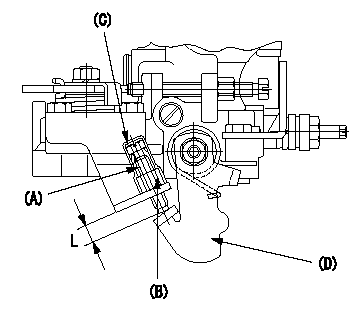
Starting Q decrease lever adjustment
Adjust using the screw (A) so that the standards are satisfied, then fix using the nut (B).
Screw (A) protrusion: L
(B) Nut (SW10, T1 after completing adjustment)
(C) Cap
(D) Stop lever
----------
L=7.4~11.1mm T1=6~9N-m(0.6~0.9kgf-m)
----------
L=7.4~11.1mm
----------
L=7.4~11.1mm T1=6~9N-m(0.6~0.9kgf-m)
----------
L=7.4~11.1mm