
Rating:
Information injection-pump assembly
ZEXEL
104760-2490
1047602490
Cross reference number
ZEXEL
104760-2490
1047602490
Zexel num
Bosch num
Firm num
Name
104760-2490
INJECTION-PUMP ASSEMBLY
Calibration Data:
Adjustment conditions
Test oil
1404 Test oil ISO4113orSAEJ967d
1404 Test oil ISO4113orSAEJ967d
Test oil temperature
degC
45
45
50
Nozzle
105780-0060
Bosch type code
NP-DN0SD1510
Nozzle holder
105780-2150
Opening pressure
MPa
13
13
13.3
Opening pressure
kgf/cm2
133
133
136
Injection pipe
157805-7320
Injection pipe
Inside diameter - outside diameter - length (mm) mm 2-6-450
Inside diameter - outside diameter - length (mm) mm 2-6-450
Joint assembly
157641-4720
Tube assembly
157641-4020
Transfer pump pressure
kPa
20
20
20
Transfer pump pressure
kgf/cm2
0.2
0.2
0.2
Direction of rotation (viewed from drive side)
Right R
Right R
Injection timing adjustment
Pump speed
r/min
1200
1200
1200
Average injection quantity
mm3/st.
32
31.6
32.4
Difference in delivery
mm3/st.
2
Basic
*
Oil temperature
degC
50
48
52
Injection timing adjustment_02
Pump speed
r/min
600
600
600
Average injection quantity
mm3/st.
30.8
28.3
33.3
Oil temperature
degC
50
48
52
Injection timing adjustment_03
Pump speed
r/min
900
900
900
Average injection quantity
mm3/st.
31.8
29.8
33.8
Oil temperature
degC
50
48
52
Injection timing adjustment_04
Pump speed
r/min
1200
1200
1200
Average injection quantity
mm3/st.
32
31
33
Difference in delivery
mm3/st.
2.5
Basic
*
Oil temperature
degC
50
48
52
Injection timing adjustment_05
Pump speed
r/min
1800
1800
1800
Average injection quantity
mm3/st.
32
30
34
Oil temperature
degC
50
48
52
Injection timing adjustment_06
Pump speed
r/min
2300
2300
2300
Average injection quantity
mm3/st.
33.2
31.2
35.2
Oil temperature
degC
52
50
54
Injection timing adjustment_07
Pump speed
r/min
2500
2500
2500
Average injection quantity
mm3/st.
33.3
30.8
35.8
Oil temperature
degC
55
52
58
Injection quantity adjustment
Pump speed
r/min
2600
2600
2600
Average injection quantity
mm3/st.
27
25
29
Difference in delivery
mm3/st.
4.5
Basic
*
Oil temperature
degC
55
52
58
Injection quantity adjustment_02
Pump speed
r/min
2600
2600
2600
Average injection quantity
mm3/st.
27
23.5
30.5
Difference in delivery
mm3/st.
5
Basic
*
Oil temperature
degC
55
52
58
Injection quantity adjustment_03
Pump speed
r/min
2800
2800
2800
Average injection quantity
mm3/st.
6.5
Oil temperature
degC
55
52
58
Governor adjustment
Pump speed
r/min
290
290
290
Average injection quantity
mm3/st.
9
8
10
Difference in delivery
mm3/st.
1.1
Basic
*
Oil temperature
degC
48
46
50
Governor adjustment_02
Pump speed
r/min
290
290
290
Average injection quantity
mm3/st.
9
7
11
Difference in delivery
mm3/st.
1.8
Basic
*
Oil temperature
degC
48
46
50
Boost compensator adjustment
Pump speed
r/min
600
600
600
Average injection quantity
mm3/st.
14.2
7.7
20.7
Oil temperature
degC
50
48
52
Lever angle (shim thickness)
mm
7.7
7.65
7.75
Remarks
From idle
From idle
Boost compensator adjustment_02
Pump speed
r/min
900
900
900
Average injection quantity
mm3/st.
7.3
0.3
14.3
Oil temperature
degC
50
48
52
Lever angle (shim thickness)
mm
7.7
7.65
7.75
Remarks
From idle
From idle
Timer adjustment
Pump speed
r/min
100
100
100
Average injection quantity
mm3/st.
40
40
Difference in delivery
mm3/st.
15
Basic
*
Oil temperature
degC
48
46
50
Timer adjustment_02
Pump speed
r/min
100
100
100
Average injection quantity
mm3/st.
40
40
Difference in delivery
mm3/st.
17
Oil temperature
degC
48
46
50
Speed control lever angle
Pump speed
r/min
290
290
290
Average injection quantity
mm3/st.
4
Oil temperature
degC
48
46
50
Remarks
Magnet OFF at idling position
Magnet OFF at idling position
Speed control lever angle_02
Pump speed
r/min
900
900
900
Average injection quantity
mm3/st.
0
0
0
Oil temperature
degC
50
48
52
Remarks
Magnet OFF at full-load position
Magnet OFF at full-load position
0000000901
Pump speed
r/min
900
900
900
Overflow quantity
cm3/min
390
260
520
Oil temperature
degC
50
48
52
Stop lever angle
Pump speed
r/min
900
900
900
Pressure
kPa
373
344
402
Pressure
kgf/cm2
3.8
3.5
4.1
Basic
*
Oil temperature
degC
50
48
52
Stop lever angle_02
Pump speed
r/min
900
900
900
Pressure
kPa
373
334
412
Pressure
kgf/cm2
3.8
3.4
4.2
Basic
*
Oil temperature
degC
50
48
52
Stop lever angle_03
Pump speed
r/min
1800
1800
1800
Pressure
kPa
579
540
618
Pressure
kgf/cm2
5.9
5.5
6.3
Oil temperature
degC
50
48
52
Stop lever angle_04
Pump speed
r/min
2500
2500
2500
Pressure
kPa
745
706
784
Pressure
kgf/cm2
7.6
7.2
8
Oil temperature
degC
55
52
58
0000001101
Pump speed
r/min
900
900
900
Timer stroke
mm
2.3
2.1
2.5
Basic
*
Oil temperature
degC
50
48
52
_02
Pump speed
r/min
900
900
900
Timer stroke
mm
2.2
1.9
2.5
Basic
*
Oil temperature
degC
50
48
52
_03
Pump speed
r/min
1200
1200
1200
Timer stroke
mm
3.7
3.3
4.1
Oil temperature
degC
50
48
52
_04
Pump speed
r/min
1800
1800
1800
Timer stroke
mm
6.9
6.3
7.5
Oil temperature
degC
50
48
52
_05
Pump speed
r/min
2300
2300
2300
Timer stroke
mm
8.95
8.5
9.4
Oil temperature
degC
52
50
54
0000001201
Max. applied voltage
V
8
8
8
Test voltage
V
13
12
14
Timing setting
K dimension
mm
3.3
3.2
3.4
KF dimension
mm
7.24
7.14
7.34
MS dimension
mm
1.8
1.7
1.9
Control lever angle alpha
deg.
23
19
27
Control lever angle beta
deg.
42
37
47
Test data Ex:
0000001801 POTENTIOMETER ADJUSTMENT
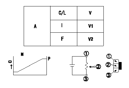
Potentiometer adjustment standards (BOSCH piping)
At pump speed N1 and the control lever positioned a from the idle position (gap L), calculate the voltage from the injection quantity obtained and adjust the potentiometer.
Conversion formula V+-0.03 = 0.08563Q+2.4389 (Q<13.9 (mm3/st))
V+-0.03 = 0.05225Q + 2.9013 [Q>=13.9(mm3/st)]
A:Performance standards (applied voltage Vi)
C/L: control lever position
I:Idle
F:Full speed
M:Connecting diagram for the potentiometer
O:Output
P:Output when (2) and (3) connected.
----------
N1=600(r/min) a=14.4(deg) L=7.7(mm) Vi=10(V)
----------
V1=0.34++(V) V2=6.41~10(V)
----------
N1=600(r/min) a=14.4(deg) L=7.7(mm) Vi=10(V)
----------
V1=0.34++(V) V2=6.41~10(V)
0000001901 W-CSD ADJUSTMENT
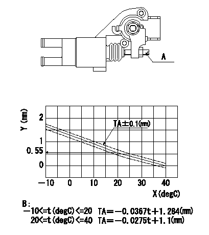
Adjustment of the W-CSD
Adjust the timer stroke using the screw so that it is as determined from the graph.
Caution: The temperature of the wax at adjustment must not exceed a.
A:Screw
B:Timer stroke graph
X:Temperature t
Y:Timer stroke TA
----------
a=30degC
----------
----------
a=30degC
----------
0000002001 DASHPOT ADJUSTMENT
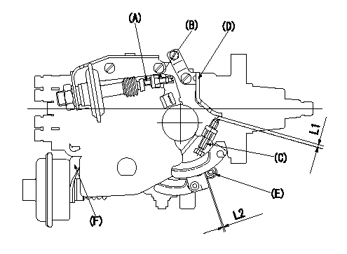
(1)Adjustment of the dash pot
1. Insert a block gauge L1 between the idle set screw (C) and the bracket (D).
2. In the above condition, adjust the locknut (B) so that the dashpot adjusting (A) contacts the pushrod, and then fix the locknut (Tightening torque T).
3.The dashpot and control lever contact faces must be smooth. Confirm that the control lever returns to the idle position.
(2)ISC actuator installation
In the idle position, fix the actuator bracket (F) so that the clearance between the control lever and the ISC lever roller (E) is L2.
----------
L1=2.7+-0.05(mm) L2=1.0+1.0-0.5(mm) T=5.9~8.8N?m(0.6~0.9(kgf?m))
----------
L1=2.7+-0.05(mm) L2=1.0+1.0-0.5(mm)
----------
L1=2.7+-0.05(mm) L2=1.0+1.0-0.5(mm) T=5.9~8.8N?m(0.6~0.9(kgf?m))
----------
L1=2.7+-0.05(mm) L2=1.0+1.0-0.5(mm)
Have questions with 104760-2490?
Group cross 104760-2490 ZEXEL
104760-2490
INJECTION-PUMP ASSEMBLY