
Rating:
Information injection-pump assembly
ZEXEL
104760-2050
1047602050
Cross reference number
ZEXEL
104760-2050
1047602050
Zexel num
Bosch num
Firm num
Name
104760-2050
INJECTION-PUMP ASSEMBLY
Calibration Data:
Adjustment conditions
(Note)
For Japan: year/month/day (change sequence) 1983/9/12 (2)
For Japan: year/month/day (change sequence) 1983/9/12 (2)
Test oil
1404 Test oil ISO4113orSAEJ967d
1404 Test oil ISO4113orSAEJ967d
Test oil temperature
degC
45
45
50
Nozzle
105000-2010
Bosch type code
NP-DN12SD12TT
Nozzle holder
105780-2080
Opening pressure
MPa
14.7
14.7
15.19
Opening pressure
kgf/cm2
150
150
155
Injection pipe
Inside diameter - outside diameter - length (mm) mm 2-6-840
Inside diameter - outside diameter - length (mm) mm 2-6-840
Transfer pump pressure
kPa
20
20
20
Transfer pump pressure
kgf/cm2
0.2
0.2
0.2
Direction of rotation (viewed from drive side)
Right R
Right R
(Solenoid timer adjustment condition)
ON
Injection timing adjustment
Pump speed
r/min
1200
1200
1200
Average injection quantity
mm3/st.
31.3
30.8
31.8
Difference in delivery
mm3/st.
2.5
Basic
*
Injection timing adjustment_02
Pump speed
r/min
2700
2700
2700
Average injection quantity
mm3/st.
11.7
8.7
14.7
Injection timing adjustment_03
Pump speed
r/min
2300
2300
2300
Average injection quantity
mm3/st.
29.8
26.8
32.8
Injection timing adjustment_04
Pump speed
r/min
1200
1200
1200
Average injection quantity
mm3/st.
31.3
30.8
31.8
Injection timing adjustment_05
Pump speed
r/min
600
600
600
Average injection quantity
mm3/st.
25.7
23.7
27.7
Injection timing adjustment_06
Pump speed
r/min
1200
1200
1200
Average injection quantity
mm3/st.
30.5
30
31
Difference in delivery
mm3/st.
2.5
Basic
*
Remarks
For Japan
For Japan
Injection timing adjustment_07
Pump speed
r/min
2700
2700
2700
Average injection quantity
mm3/st.
10
6.5
13.5
Remarks
For Japan
For Japan
Injection timing adjustment_08
Pump speed
r/min
2300
2300
2300
Average injection quantity
mm3/st.
29.1
26.1
32.1
Remarks
For Japan
For Japan
Injection timing adjustment_09
Pump speed
r/min
1200
1200
1200
Average injection quantity
mm3/st.
30.5
29.5
31.5
Remarks
For Japan
For Japan
Injection timing adjustment_10
Pump speed
r/min
600
600
600
Average injection quantity
mm3/st.
25.1
23.1
27.1
Remarks
For Japan
For Japan
Injection quantity adjustment
Pump speed
r/min
2700
2700
2700
Average injection quantity
mm3/st.
11.7
8.7
14.7
Basic
*
Injection quantity adjustment_02
Pump speed
r/min
2800
2800
2800
Average injection quantity
mm3/st.
5
Injection quantity adjustment_03
Pump speed
r/min
2700
2700
2700
Average injection quantity
mm3/st.
10
7
13
Basic
*
Remarks
For Japan
For Japan
Injection quantity adjustment_04
Pump speed
r/min
2800
2800
2800
Average injection quantity
mm3/st.
5
Remarks
For Japan
For Japan
Governor adjustment
Pump speed
r/min
350
350
350
Average injection quantity
mm3/st.
8.4
6.9
9.9
Difference in delivery
mm3/st.
3
Basic
*
Governor adjustment_02
Pump speed
r/min
350
350
350
Average injection quantity
mm3/st.
8.6
7.1
10.1
Governor adjustment_03
Pump speed
r/min
500
500
500
Average injection quantity
mm3/st.
4
Governor adjustment_04
Pump speed
r/min
350
350
350
Average injection quantity
mm3/st.
8.2
6.7
9.7
Difference in delivery
mm3/st.
3
Basic
*
Remarks
For Japan
For Japan
Governor adjustment_05
Pump speed
r/min
350
350
350
Average injection quantity
mm3/st.
8.2
6.2
10.2
Remarks
For Japan
For Japan
Governor adjustment_06
Pump speed
r/min
500
500
500
Average injection quantity
mm3/st.
4
Remarks
For Japan
For Japan
Timer adjustment
Pump speed
r/min
100
100
100
Average injection quantity
mm3/st.
49.1
44.1
54.1
Basic
*
Remarks
Refer to additional devices.
Refer to additional devices.
Timer adjustment_02
Pump speed
r/min
100
100
100
Average injection quantity
mm3/st.
47.8
42.8
52.8
Basic
*
Remarks
For Japan: refer to additional devices
For Japan: refer to additional devices
Speed control lever angle
Pump speed
r/min
350
350
350
Average injection quantity
mm3/st.
0
0
0
Remarks
Magnet OFF
Magnet OFF
Speed control lever angle_02
Pump speed
r/min
350
350
350
Average injection quantity
mm3/st.
0
0
0
Remarks
For Japan: Magnet OFF
For Japan: Magnet OFF
0000000901
Pump speed
r/min
1200
1200
1200
Overflow quantity
cm3/min
400
270
530
_02
Pump speed
r/min
1200
1200
1200
Overflow quantity
cm3/min
400
270
530
Remarks
For Japan
For Japan
Stop lever angle
Pump speed
r/min
1800
1800
1800
Pressure with S/T ON
kPa
608
579
637
Pressure with S/T ON
kgf/cm2
6.2
5.9
6.5
Basic
*
Stop lever angle_02
Pump speed
r/min
800
800
800
Pressure with S/T ON
kPa
382.5
353
412
Pressure with S/T ON
kgf/cm2
3.9
3.6
4.2
Stop lever angle_03
Pump speed
r/min
1800
1800
1800
Pressure with S/T ON
kPa
608
579
637
Pressure with S/T ON
kgf/cm2
6.2
5.9
6.5
Pressure with S/T OFF
kPa
539.5
510
569
Pressure with S/T OFF
kgf/cm2
5.5
5.2
5.8
Stop lever angle_04
Pump speed
r/min
2500
2500
2500
Pressure with S/T ON
kPa
755.5
726
785
Pressure with S/T ON
kgf/cm2
7.7
7.4
8
Stop lever angle_05
Pump speed
r/min
1800
1800
1800
Pressure with S/T ON
kPa
588.5
559
618
Pressure with S/T ON
kgf/cm2
6
5.7
6.3
Basic
*
Remarks
For Japan
For Japan
Stop lever angle_06
Pump speed
r/min
800
800
800
Pressure with S/T ON
kPa
363
324
402
Pressure with S/T ON
kgf/cm2
3.7
3.3
4.1
Remarks
For Japan
For Japan
Stop lever angle_07
Pump speed
r/min
1800
1800
1800
Pressure with S/T ON
kPa
588.5
549
628
Pressure with S/T ON
kgf/cm2
6
5.6
6.4
Pressure with S/T OFF
kPa
520
481
559
Pressure with S/T OFF
kgf/cm2
5.3
4.9
5.7
Remarks
For Japan
For Japan
Stop lever angle_08
Pump speed
r/min
2500
2500
2500
Pressure with S/T ON
kPa
735.5
696
775
Pressure with S/T ON
kgf/cm2
7.5
7.1
7.9
Remarks
For Japan
For Japan
0000001101
Pump speed
r/min
1200
1200
1200
Timer stroke with S/T ON
mm
3.8
3.5
4.1
Basic
*
_02
Pump speed
r/min
1200
1200
1200
Timer stroke with S/T ON
mm
3.8
3.5
4.1
Timer stroke with S/T OFF
mm
3.1
2.8
3.4
_03
Pump speed
r/min
1800
1800
1800
Timer stroke with S/T ON
mm
5.9
5.3
6.5
_04
Pump speed
r/min
2500
2500
2500
Timer stroke with S/T ON
mm
7.35
6.9
7.8
_05
Pump speed
r/min
1200
1200
1200
Timer stroke with S/T ON
mm
3.7
3.4
4
Basic
*
Remarks
For Japan
For Japan
_06
Pump speed
r/min
1200
1200
1200
Timer stroke with S/T ON
mm
3.7
3.3
4.1
Timer stroke with S/T OFF
mm
3
2.6
3.4
Remarks
For Japan
For Japan
_07
Pump speed
r/min
1800
1800
1800
Timer stroke with S/T ON
mm
5.8
5.2
6.4
Remarks
For Japan
For Japan
_08
Pump speed
r/min
2500
2500
2500
Timer stroke with S/T ON
mm
7.35
6.9
7.8
Remarks
For Japan
For Japan
0000001201
Max. applied voltage
V
8
8
8
Test voltage
V
13
12
14
0000001501
Pump speed
r/min
1200
1200
1200
Atmospheric pressure difference
kPa
-18.7
-18.7
-18.7
Atmospheric pressure difference
mmHg
-140
-140
-140
Decrease qty
mm3/st.
4.5
4
5
Basic
*
_02
Pump speed
r/min
1200
1200
1200
Atmospheric pressure difference
kPa
-18.7
-18.7
-18.7
Atmospheric pressure difference
mmHg
-140
-140
-140
Decrease qty
mm3/st.
4.5
3
6
_03
Pump speed
r/min
1200
1200
1200
Atmospheric pressure difference
kPa
-18.7
-18.7
-18.7
Atmospheric pressure difference
mmHg
-140
-140
-140
Decrease qty
mm3/st.
4.5
4
5
Basic
*
Remarks
For Japan
For Japan
_04
Pump speed
r/min
1200
1200
1200
Atmospheric pressure difference
kPa
-18.7
-18.7
-18.7
Atmospheric pressure difference
mmHg
-140
-140
-140
Decrease qty
mm3/st.
4.5
3
6
Remarks
For Japan
For Japan
Timing setting
K dimension
mm
3.3
3.2
3.4
KF dimension
mm
6.64
6.54
6.74
MS dimension
mm
1.8
1.7
1.9
Control lever angle alpha
deg.
23
19
27
Control lever angle beta
deg.
44
39
49
Test data Ex:
0000001501 ANEROID COMPENSATOR
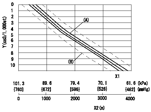
ACS adjustment
Full load injection quantity at high altitudes and ACS adjusting method
1. Full load injection quantity adjustment
(1)Remove the ACS cover and remove the bellows and adjusting shim.
(2)Perform all adjustments as per the adjustment standard except for ACS adjustment.
2. ACS adjustment
(1)Assemble the ACS cover, bellows and adjusting shim.
(2)At pump speed N1, adjust using a shim to obtain the decrease for the altitude shown in the table.
X1 = atmospheric pressure
X2 = altitude
Y = decrease quantity
(A) = adjustment value
(B) = test value
----------
N1=1200r/min
----------
----------
N1=1200r/min
----------
0000001801 W-CSD ADJUSTMENT
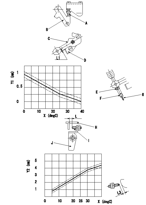
Adjustment of the W-CSD
1. Fixing the control lever's starting injection quantity adjusting bolt
Adjust the bolt so that the starting injection quantity is within the adjustment values, then fix.
2. Fixing the CSD lever stopper
At roller holder advance angle a adjust the lever shaft ball pin so that it contacts the roller holder.
At this time, fix the stopper so that the distance from the CSD lever is L1.
3. Fixing the wire CSD lever
Fix the wire at the CSD lever position for timer lift determined from the graph.
4. FICD lever screw adjustment
After fixing the W-CSD lever, move the control lever from the idle position to position L3 (see figure).
In this position, fix the screw so that the clearance between the control lever and the screw is L as determined from the graph.
Caution: After fixing the screw, the distance must be L2 or more when the control lever and the head of the screw contact at position b. If not L2 or more, replace the screw with a shorter one (select part no. 146620-1400 or 146620-2800).
A = adjusting bolt
B = stop lever
C = CSD lever
D = stopper
E = lock screw
F = lock bolt
G = wire
H = control lever
I = screw
J = FICD lever
Y1 = timer lift TA (tolerance+-0.1)
Y2 = distance L (tolerance +-0.2)
X = wax temperature t (room temperature)
----------
L1=0.5+2mm L2=0.2mm L3=3.2mm a=0deg
----------
L1=0.5+2mm L3=3.2mm
----------
L1=0.5+2mm L2=0.2mm L3=3.2mm a=0deg
----------
L1=0.5+2mm L3=3.2mm
0000001901 POTENTIOMETER ADJUSTMENT
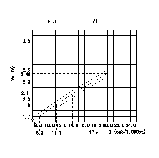
Adjustment of the potentiometer
At pump speed N = N1 and with the control lever angle at a from the idle position (corresponding to a shim thickness of L), convert the injection quantity obtained to a voltage value using the graph and adjust the potentiometer.
Caution: Confirm that the voltage increases when the control lever is turned to the full speed side.
E:J = formula
Vi:Applied voltage
Vo = output voltage
Q = injection quantity
----------
N1=700r/min a=-deg L=6.6mm
----------
J=- (V) Vi=10V
----------
N1=700r/min a=-deg L=6.6mm
----------
J=- (V) Vi=10V
Have questions with 104760-2050?
Group cross 104760-2050 ZEXEL
Nissan
Nissan
104760-2050
INJECTION-PUMP ASSEMBLY