Rating:
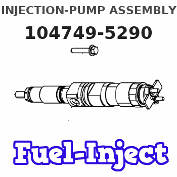
Information injection-pump assembly
ZEXEL
104749-5290
1047495290
Cross reference number
ZEXEL
104749-5290
1047495290
Zexel num
Bosch num
Firm num
Name
104749-5290
INJECTION-PUMP ASSEMBLY
Calibration Data:
Adjustment conditions
Test oil
1404 Test oil ISO4113orSAEJ967d
1404 Test oil ISO4113orSAEJ967d
Test oil temperature
degC
45
45
50
Nozzle
105780-0060
Bosch type code
NP-DN0SD1510
Nozzle holder
105780-2150
Opening pressure
MPa
13
13
13.3
Opening pressure
kgf/cm2
133
133
136
Injection pipe
157805-7320
Injection pipe
Inside diameter - outside diameter - length (mm) mm 2-6-450
Inside diameter - outside diameter - length (mm) mm 2-6-450
Joint assembly
157641-4720
Tube assembly
157641-4020
Transfer pump pressure
kPa
20
20
20
Transfer pump pressure
kgf/cm2
0.2
0.2
0.2
Direction of rotation (viewed from drive side)
Right R
Right R
Injection timing adjustment
Pump speed
r/min
900
900
900
Boost pressure
kPa
40
38.7
41.3
Boost pressure
mmHg
300
290
310
Average injection quantity
mm3/st.
47.4
46.9
47.9
Difference in delivery
mm3/st.
3.5
Basic
*
Oil temperature
degC
50
48
52
Remarks
CBS
CBS
Injection timing adjustment_02
Pump speed
r/min
1500
1500
1500
Boost pressure
kPa
72
70.7
73.3
Boost pressure
mmHg
540
530
550
Average injection quantity
mm3/st.
52.3
51.8
52.8
Difference in delivery
mm3/st.
3.5
Basic
*
Oil temperature
degC
50
48
52
Remarks
Full
Full
Injection timing adjustment_03
Pump speed
r/min
550
550
550
Boost pressure
kPa
0
0
0
Boost pressure
mmHg
0
0
0
Average injection quantity
mm3/st.
39.6
36.6
42.6
Oil temperature
degC
50
48
52
Injection timing adjustment_04
Pump speed
r/min
750
750
750
Boost pressure
kPa
31.3
30
32.6
Boost pressure
mmHg
235
225
245
Average injection quantity
mm3/st.
46.9
46.9
46.9
Oil temperature
degC
50
48
52
Injection timing adjustment_05
Pump speed
r/min
900
900
900
Boost pressure
kPa
40
38.7
41.3
Boost pressure
mmHg
300
290
310
Average injection quantity
mm3/st.
47.4
46.4
48.4
Difference in delivery
mm3/st.
3.5
Basic
*
Oil temperature
degC
50
48
52
Injection timing adjustment_06
Pump speed
r/min
1500
1500
1500
Boost pressure
kPa
0
0
0
Boost pressure
mmHg
0
0
0
Average injection quantity
mm3/st.
37.4
34.9
39.9
Oil temperature
degC
50
48
52
Injection timing adjustment_07
Pump speed
r/min
1500
1500
1500
Boost pressure
kPa
72
70.7
73.3
Boost pressure
mmHg
540
530
550
Average injection quantity
mm3/st.
52.3
51.3
53.3
Difference in delivery
mm3/st.
3.5
Basic
*
Oil temperature
degC
50
48
52
Injection timing adjustment_08
Pump speed
r/min
2250
2250
2250
Boost pressure
kPa
72
70.7
73.3
Boost pressure
mmHg
540
530
550
Average injection quantity
mm3/st.
50.9
47.9
53.9
Oil temperature
degC
52
50
54
Injection quantity adjustment
Pump speed
r/min
2750
2750
2750
Boost pressure
kPa
72
70.7
73.3
Boost pressure
mmHg
540
530
550
Average injection quantity
mm3/st.
24.4
23.4
25.4
Difference in delivery
mm3/st.
5.5
Basic
*
Oil temperature
degC
55
52
58
Injection quantity adjustment_02
Pump speed
r/min
2750
2600
2900
Boost pressure
kPa
72
70.7
73.3
Boost pressure
mmHg
540
530
550
Average injection quantity
mm3/st.
24.4
23.4
25.4
Difference in delivery
mm3/st.
5.5
Oil temperature
degC
55
52
58
Injection quantity adjustment_03
Pump speed
r/min
2950
2950
2950
Boost pressure
kPa
72
70.7
73.3
Boost pressure
mmHg
540
530
550
Average injection quantity
mm3/st.
4
Oil temperature
degC
55
52
58
Remarks
Insert a 1 mm shim between the control lever and the full speed position and measure the injection quantity.
Insert a 1 mm shim between the control lever and the full speed position and measure the injection quantity.
Governor adjustment
Pump speed
r/min
425
425
425
Boost pressure
kPa
0
0
0
Boost pressure
mmHg
0
0
0
Average injection quantity
mm3/st.
8.9
6.9
10.9
Difference in delivery
mm3/st.
2
Basic
*
Oil temperature
degC
48
46
50
Governor adjustment_02
Pump speed
r/min
425
425
425
Boost pressure
kPa
0
0
0
Boost pressure
mmHg
0
0
0
Average injection quantity
mm3/st.
8.9
6.9
10.9
Difference in delivery
mm3/st.
2
Oil temperature
degC
48
46
50
Timer adjustment
Pump speed
r/min
150
150
150
Boost pressure
kPa
0
0
0
Boost pressure
mmHg
0
0
0
Average injection quantity
mm3/st.
40
30
50
Basic
*
Oil temperature
degC
48
46
50
Remarks
IDLE
IDLE
Timer adjustment_02
Pump speed
r/min
150
150
150
Boost pressure
kPa
0
0
0
Boost pressure
mmHg
0
0
0
Average injection quantity
mm3/st.
40
30
50
Oil temperature
degC
48
46
50
Remarks
IDLE
IDLE
Speed control lever angle
Pump speed
r/min
425
425
425
Boost pressure
kPa
0
0
0
Boost pressure
mmHg
0
0
0
Average injection quantity
mm3/st.
0
0
0
Oil temperature
degC
48
46
50
Remarks
Magnet OFF at idling position
Magnet OFF at idling position
0000000901
Pump speed
r/min
1250
1250
1250
Boost pressure
kPa
72
70.7
73.3
Boost pressure
mmHg
72
70.7
73.3
Overflow quantity
cm3/min
630
500
760
Oil temperature
degC
50
48
52
Remarks
Full
Full
_02
Pump speed
r/min
425
425
425
Boost pressure
kPa
0
0
0
Boost pressure
mmHg
0
0
0
Overflow quantity
cm3/min
330
200
460
Oil temperature
degC
48
46
50
Remarks
IDLE
IDLE
Stop lever angle
Pump speed
r/min
1250
1250
1250
Boost pressure
kPa
72
70.7
73.3
Boost pressure
mmHg
540
530
550
Pressure
kPa
412
392
432
Pressure
kgf/cm2
4.2
4
4.4
Basic
*
Oil temperature
degC
50
48
52
Stop lever angle_02
Pump speed
r/min
1250
1250
1250
Boost pressure
kPa
72
70.7
73.3
Boost pressure
mmHg
540
530
550
Pressure
kPa
412
392
432
Pressure
kgf/cm2
4.2
4
4.4
Basic
*
Oil temperature
degC
50
48
52
0000001101
Pump speed
r/min
1250
1250
1250
Boost pressure
kPa
72
70.7
73.3
Boost pressure
mmHg
540
530
550
Timer stroke
mm
4.7
4.5
4.9
Basic
*
Oil temperature
degC
50
48
52
_02
Pump speed
r/min
600
600
600
Boost pressure
kPa
72
70.7
73.3
Boost pressure
mmHg
540
530
550
Timer stroke
mm
0.5
0.1
1.5
Oil temperature
degC
50
48
52
_03
Pump speed
r/min
1250
1250
1250
Boost pressure
kPa
72
70.7
73.3
Boost pressure
mmHg
540
530
550
Timer stroke
mm
4.7
4.5
4.9
Basic
*
Oil temperature
degC
50
48
52
_04
Pump speed
r/min
1500
1500
1500
Boost pressure
kPa
72
70.7
73.3
Boost pressure
mmHg
540
530
550
Timer stroke
mm
6.3
5.9
6.7
Oil temperature
degC
50
48
52
_05
Pump speed
r/min
2000
2000
2000
Boost pressure
kPa
72
70.7
73.3
Boost pressure
mmHg
540
530
550
Timer stroke
mm
9
8.7
9.4
Oil temperature
degC
50
48
52
0000001201
Max. applied voltage
V
8
8
8
Test voltage
V
13
12
14
Timing setting
K dimension
mm
3.3
3.2
3.4
KF dimension
mm
5.8
5.7
5.9
MS dimension
mm
0.9
0.8
1
BCS stroke
mm
3.9
3.7
4.1
Control lever angle alpha
deg.
20
16
24
Control lever angle beta
deg.
40
39
41
Test data Ex:
0000001801 POTENTIOMETER ADJUSTMENT
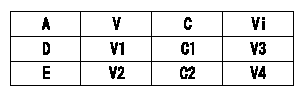
A:Lever position
V:Output voltage
C:Lever angle
Vi:Applied voltage
D:Full speed
E:Idle
----------
V1=8.34+-0.03(V) V2=(1.67(V)) C1=40+-1.5(deg) C2=0(deg) V3=10.00(V) V4=10.00(V)
----------
V1=8.34+-0.03(V) V2=(1.67(V)) C1=40+-1.5(deg) C2=0(deg) V3=10.00(V) V4=10.00(V)
----------
V1=8.34+-0.03(V) V2=(1.67(V)) C1=40+-1.5(deg) C2=0(deg) V3=10.00(V) V4=10.00(V)
----------
V1=8.34+-0.03(V) V2=(1.67(V)) C1=40+-1.5(deg) C2=0(deg) V3=10.00(V) V4=10.00(V)
0000001901 V-FICD ADJUSTMENT
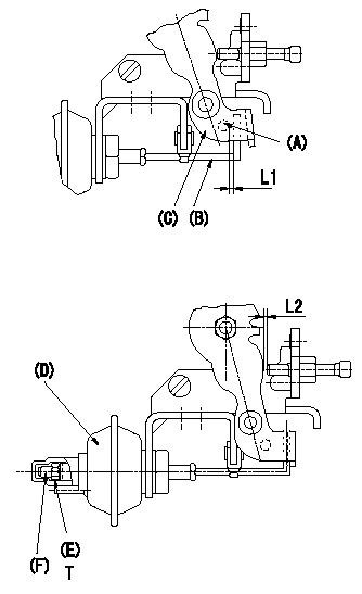
Adjustment of the V-FICD (perform with W-FICD released)
1. Adjust to obtain L1.
2. Confirm that L2 is obtained when negative pressure P1 (kPa) {P2 (mmHg)} is applied to the actuator.
Adjust the stroke using the actuator stroke adjusting screw (F).
(A): Pin
(B): Actuator shaft
(C): Control lever
(D): Actuator
(E): Lock nut (torque T)
----------
L1=1+1(mm) L2=0.84+-0.1(mm) P1=-53.3(kPa) P2=-400(mmHg)
----------
L1=1+1(mm) L2=0.84+-0.1(mm) T=1.2~1.5(N-m)(0.12~0.15(kgf-m))
----------
L1=1+1(mm) L2=0.84+-0.1(mm) P1=-53.3(kPa) P2=-400(mmHg)
----------
L1=1+1(mm) L2=0.84+-0.1(mm) T=1.2~1.5(N-m)(0.12~0.15(kgf-m))
0000002001 W-CSD ADJUSTMENT
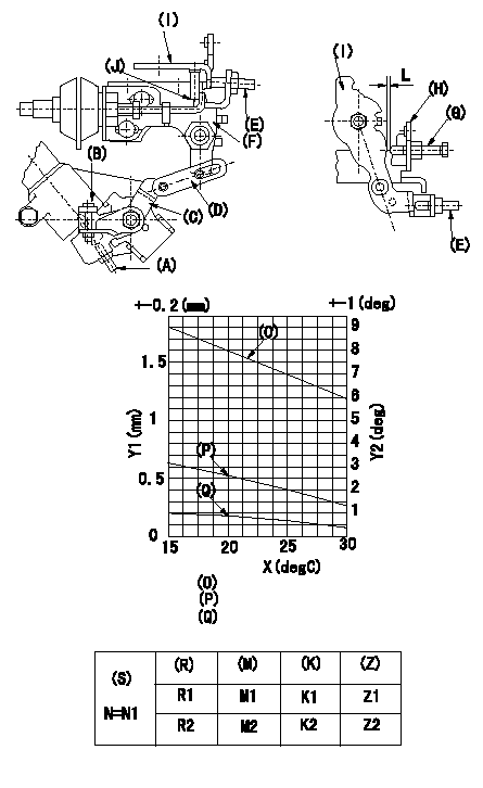
Adjustment of the W-CSD
1. Adjustment of the timer stroke
Adjust screw (A) so that the timer stroke is the value determined from the graph.
2. Adjustment of the position of the intermediate lever.
Insert a shim L between the control lever I and the idle setscrew G.
Align the intermediate lever (F) with the aligning line and fix screw intermediate lever's adjusting (E) so that it contacts the control lever.
3. Adjustment of the FICD
Insert a shim LT between the control lever I and the idle setscrew G.
Use adjusting screw (B) to fix the CSD lever (C) in the position where it operates the intermediate lever via the rod (D).
(J) Aligning mark
(O) = timer stroke adjustment (mm): TA = -0.041t+2.42
(P) Lever position (deg): theta 1 = -0.108t+4.79 (-20 deg C <= t <= 20 deg C)
Theta 2 = -0.133t + 5.29 (20 deg C =< t =< 50 deg C)
(Q) Lever position (mm): L1 = -0.035t+1.57 (-20 deg C <= t <= 20 deg C)
L2 = -0.044t + 1.75 (20 deg C =< t =< 50 deg C)
The (Q) indicates the clearance between the control lever and the idle set screw.
X:Temperature t (deg C)
Y1:Timer stroke TA (mm)
Y2:Control lever position at theta L (deg, mm)
(R) Cooling water temperature (deg C)
(S) Cooling water temperature: increase direction
N:Pump speed (r/min)
(M) Timer piston stroke (mm)
(K) Lever angle (deg)
(Z) Lever position (mm)
----------
L=1.2+-0.05(mm) LT=L+-0.05(mm) N1=500(r/min)
----------
L=1.2+-0.05(mm) LT=L+-0.05(mm) N1=500(r/min) R1=20(degC) R2=-20(degC) M1=1.9+-0.4(mm) M2=3.4+-0.6(mm) K1=3.6+-1(deg) K2=7.9+-3(deg) Z1=1.2+-0.3(mm) Z2=2.6+-1(mm)
----------
L=1.2+-0.05(mm) LT=L+-0.05(mm) N1=500(r/min)
----------
L=1.2+-0.05(mm) LT=L+-0.05(mm) N1=500(r/min) R1=20(degC) R2=-20(degC) M1=1.9+-0.4(mm) M2=3.4+-0.6(mm) K1=3.6+-1(deg) K2=7.9+-3(deg) Z1=1.2+-0.3(mm) Z2=2.6+-1(mm)
Have questions with 104749-5290?
Group cross 104749-5290 ZEXEL
Isuzu
Isuzu
104749-5290
INJECTION-PUMP ASSEMBLY