
Rating:
Information injection-pump assembly
ZEXEL
104749-2561
1047492561
Cross reference number
ZEXEL
104749-2561
1047492561
Zexel num
Bosch num
Firm num
Name
104749-2561
INJECTION-PUMP ASSEMBLY
Calibration Data:
Adjustment conditions
Test oil
1404 Test oil ISO4113orSAEJ967d
1404 Test oil ISO4113orSAEJ967d
Test oil temperature
degC
45
45
50
Nozzle
105780-0060
Bosch type code
NP-DN0SD1510
Nozzle holder
105780-2150
Opening pressure
MPa
13
13
13.3
Opening pressure
kgf/cm2
133
133
136
Injection pipe
157805-7320
Injection pipe
Inside diameter - outside diameter - length (mm) mm 2-6-450
Inside diameter - outside diameter - length (mm) mm 2-6-450
Joint assembly
157641-4720
Tube assembly
157641-4020
Transfer pump pressure
kPa
20
20
20
Transfer pump pressure
kgf/cm2
0.2
0.2
0.2
Direction of rotation (viewed from drive side)
Right R
Right R
Injection timing adjustment
Pump speed
r/min
1000
1000
1000
Average injection quantity
mm3/st.
33.9
33.4
34.4
Difference in delivery
mm3/st.
2
Basic
*
Injection timing adjustment_02
Pump speed
r/min
2600
2600
2600
Average injection quantity
mm3/st.
22.3
19.8
24.8
Injection timing adjustment_03
Pump speed
r/min
2300
2300
2300
Average injection quantity
mm3/st.
36.1
34.1
38.1
Injection timing adjustment_04
Pump speed
r/min
1800
1800
1800
Average injection quantity
mm3/st.
34.6
32.6
36.6
Injection timing adjustment_05
Pump speed
r/min
1000
1000
1000
Average injection quantity
mm3/st.
33.9
32.9
34.9
Injection timing adjustment_06
Pump speed
r/min
600
600
600
Average injection quantity
mm3/st.
33
31
35
Injection timing adjustment_07
Pump speed
r/min
400
400
400
Average injection quantity
mm3/st.
39.7
34.7
44.7
Injection quantity adjustment
Pump speed
r/min
2600
2600
2600
Average injection quantity
mm3/st.
22.3
20.3
24.3
Difference in delivery
mm3/st.
6
Basic
*
Injection quantity adjustment_02
Pump speed
r/min
2800
2800
2800
Average injection quantity
mm3/st.
7
Governor adjustment
Pump speed
r/min
350
350
350
Average injection quantity
mm3/st.
7.1
6.1
8.1
Difference in delivery
mm3/st.
2
Basic
*
Governor adjustment_02
Pump speed
r/min
500
500
500
Average injection quantity
mm3/st.
3
Governor adjustment_03
Pump speed
r/min
350
350
350
Average injection quantity
mm3/st.
7.1
5.6
8.6
Boost compensator adjustment
Pump speed
r/min
600
600
600
Average injection quantity
mm3/st.
16
11.5
20.5
Timer adjustment
Pump speed
r/min
100
100
100
Average injection quantity
mm3/st.
60
50
70
Basic
*
Speed control lever angle
Pump speed
r/min
350
350
350
Average injection quantity
mm3/st.
0
0
0
Remarks
Magnet OFF
Magnet OFF
0000000901
Pump speed
r/min
900
900
900
Overflow quantity
cm3/min
330
198
462
Stop lever angle
Pump speed
r/min
900
900
900
Pressure
kPa
343.5
314
373
Pressure
kgf/cm2
3.5
3.2
3.8
Basic
*
Stop lever angle_02
Pump speed
r/min
900
900
900
Pressure
kPa
343.5
314
373
Pressure
kgf/cm2
3.5
3.2
3.8
Stop lever angle_03
Pump speed
r/min
1800
1800
1800
Pressure
kPa
539.5
510
569
Pressure
kgf/cm2
5.5
5.2
5.8
Stop lever angle_04
Pump speed
r/min
2300
2300
2300
Pressure
kPa
657
628
686
Pressure
kgf/cm2
6.7
6.4
7
0000001101
Pump speed
r/min
900
900
900
Timer stroke
mm
1.5
1.3
1.7
Basic
*
_02
Pump speed
r/min
900
900
900
Timer stroke
mm
1.5
1.2
1.8
_03
Pump speed
r/min
1800
1800
1800
Timer stroke
mm
6.5
5.8
7.2
_04
Pump speed
r/min
2300
2300
2300
Timer stroke
mm
8.5
8
9
0000001201
Max. applied voltage
V
8
8
8
Test voltage
V
13
12
14
Timing setting
K dimension
mm
3.3
3.2
3.4
KF dimension
mm
5.8
5.7
5.9
MS dimension
mm
1.2
1.1
1.3
Control lever angle alpha
deg.
25
21
29
Control lever angle beta
deg.
41
36
46
Control lever angle gamma
deg.
11
10.5
11.5
Test data Ex:
0000001801 M-CSD ADJUSTMENT
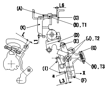
M-CSD adjustment
1. Fixing intermediate lever screw (A) [roller (E) must not contact intermediate lever (D)]
(1)Hold the control lever C in the idling position.
(2)Insert a block gauge (thickness gauge) L1 between the intermediate lever D and the intermediate lever bracket J and fix intermediate lever D.
(3)At this time, adjust screw (A) so that it is horizontal and the clearance between screw (A) and the control lever (C) is L2. Then, fix using nut (B).
2. Fixing the M-CSD stopper (I)
(1)At roller holder advance angle b, adjust the lever shaft ball pin so that it contacts the roller holder.
(2)At this time, fix the stopper I using the screw J where the distance a between the CSD lever F and the stopper is L3.
(3)Pull the CSD lever F in the direction X until it contacts the stopper I and confirm that the timer stroke is L4.
3. Screw G adjustment (without a block gauge L5 at a)
(1)Adjust the screw (G) so that the clearance between the screw (A) adjusted in 1. above and the control lever (C) is at least L6. Then, fix using the nut (H).
(2)Confirm that the control lever shim thickness L = L7.
----------
L1=1.5mm L2=1mm L3=(4.5)mm L4=1.23+-0.2mm L5=(4.5)mm L6=1mm L7=5.8+-0.3mm b=0deg
----------
T1=6~9N-m(0.6~0.9kgf-m) T2=4.9~7N-m(0.5~0.7kgf-m) T3=2~2.9N-m(0.2~0.3kgf-m) L1=1.5mm L3=Approx. 4.5mm L6=Above 1mm
----------
L1=1.5mm L2=1mm L3=(4.5)mm L4=1.23+-0.2mm L5=(4.5)mm L6=1mm L7=5.8+-0.3mm b=0deg
----------
T1=6~9N-m(0.6~0.9kgf-m) T2=4.9~7N-m(0.5~0.7kgf-m) T3=2~2.9N-m(0.2~0.3kgf-m) L1=1.5mm L3=Approx. 4.5mm L6=Above 1mm
0000001901 DASHPOT ADJUSTMENT
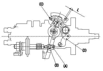
Adjustment of the dash pot
1. Insert a block gauge L (thickness gauge) between the idle set screw (C) and the control lever (D).
2. In the above condition, adjust the dashpot adjusting screw (A) so that it contacts the pushrod, and then fix it using the locknut (B).
Note:
(1)The adjusting screw and pushrod contact faces must be smooth.
(2)Confirm that the control lever returns to the idling position.
----------
L=3.8+-0.05mm
----------
L=3.8+-0.05mm
----------
L=3.8+-0.05mm
----------
L=3.8+-0.05mm
Have questions with 104749-2561?
Group cross 104749-2561 ZEXEL
Nissan
Nissan
Nissan
Nissan
Nitco(Misa)
Nissan
104749-2561
INJECTION-PUMP ASSEMBLY