
Rating:
Information injection-pump assembly
BOSCH
9 460 610 370
9460610370
ZEXEL
104749-2330
1047492330
Cross reference number
BOSCH
9 460 610 370
9460610370
ZEXEL
104749-2330
1047492330
Zexel num
Bosch num
Firm num
Name
104749-2330
9 460 610 370
INJECTION-PUMP ASSEMBLY
Calibration Data:
Adjustment conditions
Test oil
1404 Test oil ISO4113orSAEJ967d
1404 Test oil ISO4113orSAEJ967d
Test oil temperature
degC
45
45
50
Nozzle
105780-0060
Bosch type code
NP-DN0SD1510
Nozzle holder
105780-2150
Opening pressure
MPa
13
13
13.3
Opening pressure
kgf/cm2
133
133
136
Injection pipe
157805-7320
Injection pipe
Inside diameter - outside diameter - length (mm) mm 2-6-450
Inside diameter - outside diameter - length (mm) mm 2-6-450
Joint assembly
157641-4720
Tube assembly
157641-4020
Transfer pump pressure
kPa
20
20
20
Transfer pump pressure
kgf/cm2
0.2
0.2
0.2
Direction of rotation (viewed from drive side)
Right R
Right R
Injection timing adjustment
Pump speed
r/min
900
900
900
Average injection quantity
mm3/st.
30.4
30
30.8
Difference in delivery
mm3/st.
2
Basic
*
Injection timing adjustment_02
Pump speed
r/min
2700
2700
2700
Average injection quantity
mm3/st.
14
11.5
16.5
Injection timing adjustment_03
Pump speed
r/min
2500
2500
2500
Average injection quantity
mm3/st.
34.1
32
36.2
Injection timing adjustment_04
Pump speed
r/min
2300
2300
2300
Average injection quantity
mm3/st.
34.9
32.9
36.9
Injection timing adjustment_05
Pump speed
r/min
1800
1800
1800
Average injection quantity
mm3/st.
34.4
32.4
36.4
Injection timing adjustment_06
Pump speed
r/min
1200
1200
1200
Average injection quantity
mm3/st.
34.7
33.2
36.2
Injection timing adjustment_07
Pump speed
r/min
900
900
900
Average injection quantity
mm3/st.
30.4
29.5
31.3
Injection timing adjustment_08
Pump speed
r/min
600
600
600
Average injection quantity
mm3/st.
31.4
29.6
33.2
Injection quantity adjustment
Pump speed
r/min
2700
2700
2700
Average injection quantity
mm3/st.
14
12
16
Difference in delivery
mm3/st.
4.5
Basic
*
Injection quantity adjustment_02
Pump speed
r/min
2800
2800
2800
Average injection quantity
mm3/st.
6
Governor adjustment
Pump speed
r/min
350
350
350
Average injection quantity
mm3/st.
7.4
6.4
8.4
Difference in delivery
mm3/st.
1.7
Basic
*
Governor adjustment_02
Pump speed
r/min
350
350
350
Average injection quantity
mm3/st.
7.4
6.4
8.4
Governor adjustment_03
Pump speed
r/min
500
500
500
Average injection quantity
mm3/st.
4.5
Boost compensator adjustment
Pump speed
r/min
600
600
600
Average injection quantity
mm3/st.
13.9
7.4
20.4
Remarks
Refer to additional devices.
Refer to additional devices.
Timer adjustment
Pump speed
r/min
100
100
100
Average injection quantity
mm3/st.
55
45
65
Basic
*
Speed control lever angle
Pump speed
r/min
350
350
350
Average injection quantity
mm3/st.
0
0
0
Remarks
Magnet OFF
Magnet OFF
Speed control lever angle_02
Pump speed
r/min
900
900
900
Average injection quantity
mm3/st.
0
0
0
Remarks
Magnet OFF
Magnet OFF
0000000901
Pump speed
r/min
900
900
900
Overflow quantity
cm3/min
330
198
462
Stop lever angle
Pump speed
r/min
900
900
900
Pressure
kPa
372.5
343
402
Pressure
kgf/cm2
3.8
3.5
4.1
Basic
*
Stop lever angle_02
Pump speed
r/min
900
900
900
Pressure
kPa
372.5
343
402
Pressure
kgf/cm2
3.8
3.5
4.1
Stop lever angle_03
Pump speed
r/min
1800
1800
1800
Pressure
kPa
578.5
549
608
Pressure
kgf/cm2
5.9
5.6
6.2
Stop lever angle_04
Pump speed
r/min
2300
2300
2300
Pressure
kPa
686.5
657
716
Pressure
kgf/cm2
7
6.7
7.3
0000001101
Pump speed
r/min
900
900
900
Timer stroke
mm
3.7
3.5
3.9
Basic
*
_02
Pump speed
r/min
900
900
900
Timer stroke
mm
3.7
3.5
3.9
_03
Pump speed
r/min
1200
1200
1200
Timer stroke
mm
5.3
4.9
5.7
_04
Pump speed
r/min
1800
1800
1800
Timer stroke
mm
8.5
7.9
9.1
_05
Pump speed
r/min
2300
2300
2300
Timer stroke
mm
10.65
10.2
11.1
0000001201
Max. applied voltage
V
8
8
8
Test voltage
V
13
12
14
0000001401
Pump speed
r/min
900
900
900
Average injection quantity
mm3/st.
17
16
18
Timer stroke variation dT
mm
0.65
0.45
0.85
Basic
*
Timing setting
K dimension
mm
3.3
3.2
3.4
KF dimension
mm
5.7
5.6
5.8
MS dimension
mm
0.9
0.8
1
Control lever angle alpha
deg.
25
21
29
Control lever angle beta
deg.
44
39
49
Control lever angle gamma
deg.
11
10.5
11.5
Test data Ex:
0000001801 W-CSD ADJUSTMENT
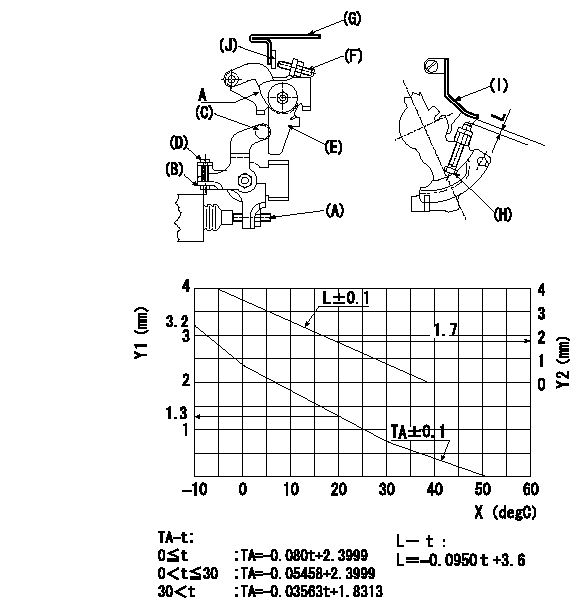
Adjustment of the W-CSD
1. Align the intermediate lever (E) with the aligning mark, position it perpendicular and fix the control lever (G) where it contacts the screw (F). Do not insert shim (H).
2. Timer advance adjustment
Adjust using screw (A) so that the timer lift is the value determined from the graph.
3. W-CSD lever adjustment
Insert a shim (J) thickness L1 between the control lever (G) and the screw (F). Turn the W-FICD lever using the screw (D) and fix screw (D) using the nut (B) where L is the dimension determined from the graph. After adjustment, remove the shim (J).
A = aligning mark
X = temperature t (deg C)
Y1 = timer stroke TA (mm)
Y2 = control lever dimension L (mm)
----------
L1=3+-0.05mm
----------
----------
L1=3+-0.05mm
----------
0000001901 A/T PLATE ADJUSTMENT
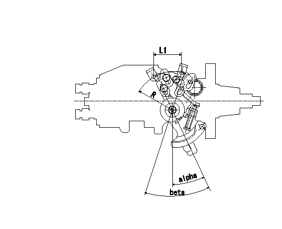
A/T wire installation plate adjustment
Confirm angle beta. Adjust the A/T wire plate, referring to angle beta in (1), (2) and (3) below.
(1)When a <= beta <= b (outermost), adjust the plate so that R = R1.
(2)Adjust the plate to obtain L1 at c <= beta <= d.
(3)When e <= beta <= f (innermost), adjust the plate so that R = R2.
Note: Measure L1 parallel to the pump center line.
----------
a=39deg b=41.5deg c=41.5deg d=46.5deg e=46.5deg f=49deg R1=64mm R2=57mm L1=41.5+-0.9mm
----------
L1=41.5+-0.9mm alpha=21~29deg beta=39~49deg
----------
a=39deg b=41.5deg c=41.5deg d=46.5deg e=46.5deg f=49deg R1=64mm R2=57mm L1=41.5+-0.9mm
----------
L1=41.5+-0.9mm alpha=21~29deg beta=39~49deg
0000002001 POTENTIOMETER ADJUSTMENT
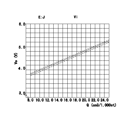
Adjustment of the potentiometer
At pump speed N = N1 and with the control lever angle at a from the idle position (corresponding to a shim thickness of L), convert the injection quantity obtained to a voltage value using the graph and adjust the potentiometer.
Caution: Confirm that the voltage increases when the control lever is turned to the full speed side.
E:J = formula
Vi:Applied voltage
Vo = output voltage
Q = injection quantity
----------
N1=600r/min a=11deg L=5.8mm Vi=10V
----------
J=Vo+-0.03=0.0916Q+3.06(14.2<=Q<=26.2cm3/1,000st) Vi=10V
----------
N1=600r/min a=11deg L=5.8mm Vi=10V
----------
J=Vo+-0.03=0.0916Q+3.06(14.2<=Q<=26.2cm3/1,000st) Vi=10V
Have questions with 104749-2330?
Group cross 104749-2330 ZEXEL
Nissan
Nissan
104749-2330
9 460 610 370
INJECTION-PUMP ASSEMBLY