
Rating:
Information injection-pump assembly
ZEXEL
104749-0321
1047490321
MAZDA
PN2213800A
pn2213800a
Cross reference number
ZEXEL
104749-0321
1047490321
MAZDA
PN2213800A
pn2213800a
Zexel num
Bosch num
Firm num
Name
Calibration Data:
Adjustment conditions
Test oil
1404 Test oil ISO4113orSAEJ967d
1404 Test oil ISO4113orSAEJ967d
Test oil temperature
degC
45
45
50
Nozzle
105000-2010
Bosch type code
NP-DN12SD12TT
Nozzle holder
105780-2080
Opening pressure
MPa
14.7
14.7
15.19
Opening pressure
kgf/cm2
150
150
155
Injection pipe
Inside diameter - outside diameter - length (mm) mm 2-6-840
Inside diameter - outside diameter - length (mm) mm 2-6-840
Transfer pump pressure
kPa
20
20
20
Transfer pump pressure
kgf/cm2
0.2
0.2
0.2
Direction of rotation (viewed from drive side)
Right R
Right R
Injection timing adjustment
Pump speed
r/min
1500
1500
1500
Average injection quantity
mm3/st.
36.1
35.6
36.6
Difference in delivery
mm3/st.
2.5
Basic
*
Injection timing adjustment_02
Pump speed
r/min
2635
2635
2635
Average injection quantity
mm3/st.
8
5
11
Injection timing adjustment_03
Pump speed
r/min
2350
2350
2350
Average injection quantity
mm3/st.
31.3
29.3
33.3
Injection timing adjustment_04
Pump speed
r/min
1500
1500
1500
Average injection quantity
mm3/st.
36.1
35.1
37.1
Injection timing adjustment_05
Pump speed
r/min
500
500
500
Average injection quantity
mm3/st.
35.2
31.2
39.2
Injection quantity adjustment
Pump speed
r/min
2635
2635
2635
Average injection quantity
mm3/st.
8
6
10
Basic
*
Injection quantity adjustment_02
Pump speed
r/min
2800
2800
2800
Average injection quantity
mm3/st.
3
Governor adjustment
Pump speed
r/min
410
410
410
Average injection quantity
mm3/st.
6
5
7
Difference in delivery
mm3/st.
2
Basic
*
Governor adjustment_02
Pump speed
r/min
410
410
410
Average injection quantity
mm3/st.
6
5
7
Timer adjustment
Pump speed
r/min
100
100
100
Average injection quantity
mm3/st.
65
55
75
Basic
*
Speed control lever angle
Pump speed
r/min
410
410
410
Average injection quantity
mm3/st.
0
0
0
Remarks
Magnet OFF
Magnet OFF
0000000901
Pump speed
r/min
1500
1500
1500
Overflow quantity
cm3/min
450
318
582
Stop lever angle
Pump speed
r/min
1500
1500
1500
Pressure
kPa
460.5
431
490
Pressure
kgf/cm2
4.7
4.4
5
Basic
*
Stop lever angle_02
Pump speed
r/min
1000
1000
1000
Pressure
kPa
323.5
294
353
Pressure
kgf/cm2
3.3
3
3.6
Stop lever angle_03
Pump speed
r/min
1500
1500
1500
Pressure
kPa
460.5
431
490
Pressure
kgf/cm2
4.7
4.4
5
Stop lever angle_04
Pump speed
r/min
2350
2350
2350
Pressure
kPa
696.5
667
726
Pressure
kgf/cm2
7.1
6.8
7.4
0000001101
Pump speed
r/min
1500
1500
1500
Timer stroke
mm
3.9
3.7
4.1
Basic
*
_02
Pump speed
r/min
1000
1000
1000
Timer stroke
mm
1.6
1
2.2
_03
Pump speed
r/min
1500
1500
1500
Timer stroke
mm
3.9
3.6
4.2
_04
Pump speed
r/min
2350
2350
2350
Timer stroke
mm
7.7
7.1
8.3
0000001201
Max. applied voltage
V
8
8
8
Test voltage
V
13
12
14
0000001401
Pump speed
r/min
1500
1500
1500
Average injection quantity
mm3/st.
32.2
31.2
33.2
Timer stroke TA
mm
3.2
3
3.4
Basic
*
_02
Pump speed
r/min
1500
1500
1500
Average injection quantity
mm3/st.
32.2
30.7
33.7
Timer stroke TA
mm
3.2
2.9
3.5
_03
Pump speed
r/min
1500
1500
1500
Average injection quantity
mm3/st.
23.1
21.6
24.6
Timer stroke TA
mm
2.2
2.2
2.2
Timing setting
K dimension
mm
3.3
3.2
3.4
KF dimension
mm
5.8
5.7
5.9
MS dimension
mm
1.5
1.4
1.6
Control lever angle alpha
deg.
25
23
27
Control lever angle beta
deg.
43
38
48
Test data Ex:
0000001801 CDS LEVER/M-CSD ADJUSTMENT
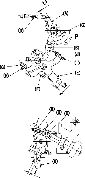
CSD lever assembly adjustment specifications
1. Adjusting and fixing the side link lever
With control lever on top of pump positioned at a, move side link lever B to contact stopper C and turn lever A lightly in direction P to eliminate any play in connecting rod D. Then, adjust length of rod D so that clearance between A and B is L1.
2. Fixing the M-CSD
Advance roller holder b, adjust lever shaft ball pin to contact roller holder. Adjust position of M-CSD lever (E) using adjusting screw (G) so that clearance between M-CSD lever (E) and stopper is L2 and fix using nut (H). Torque nut to T1.
3. M-CSD adjustment
When the CSD lever (E) is moved through its full stroke [until it contacts the other end of stopper (F)], adjust using the screw (I) so that the position of control lever (K) is c (L = L3). Then, fix using the nut (J). Torque nut (J) to T2.
L = L3 at idle to c, L = L4 at idle to d.
4. Dashpot operating position adjustment
When the control lever (K)'s position is d (L = L4), adjust the position of the screw (Q) so that the dashpot operating screw (Q) lightly contacts the end of the dashpot rod (O). Then, fix using the nut (R).
----------
a=0deg b=0deg c=9.5deg d=15.2deg L1=0.8+0.2mm L2=0.5+2mm L3=4.1+-0.5mm L4=6.4+-0.5mm T1=6~9Nm(0.6~0.9kgfm) T2=3.4~0.49Nm(0.35~0.5kgfm)
----------
L1=0.8+-0.2mm L2=0.5+2mm L=L3=4.1+-0.5mm L=L4=6.4+-0.5mm
----------
a=0deg b=0deg c=9.5deg d=15.2deg L1=0.8+0.2mm L2=0.5+2mm L3=4.1+-0.5mm L4=6.4+-0.5mm T1=6~9Nm(0.6~0.9kgfm) T2=3.4~0.49Nm(0.35~0.5kgfm)
----------
L1=0.8+-0.2mm L2=0.5+2mm L=L3=4.1+-0.5mm L=L4=6.4+-0.5mm
0000001901 DASHPOT ADJUSTMENT
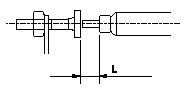
Adjustment of the dash pot
1. With the control lever in the idle position, set the operating screw so that the length of the end of the dashpot is L, then fix using the nut.
----------
L=2.3+-0.3mm
----------
L=2.3+-0.3mm
----------
L=2.3+-0.3mm
----------
L=2.3+-0.3mm