
Rating:
Information injection-pump assembly
BOSCH
9 460 610 188
9460610188
ZEXEL
104748-0134
1047480134
Cross reference number
BOSCH
9 460 610 188
9460610188
ZEXEL
104748-0134
1047480134
Zexel num
Bosch num
Firm num
Name
Calibration Data:
Adjustment conditions
Test oil
1404 Test oil ISO4113orSAEJ967d
1404 Test oil ISO4113orSAEJ967d
Test oil temperature
degC
45
45
50
Nozzle
105000-2010
Bosch type code
NP-DN12SD12TT
Nozzle holder
105780-2080
Opening pressure
MPa
14.7
14.7
15.19
Opening pressure
kgf/cm2
150
150
155
Injection pipe
Inside diameter - outside diameter - length (mm) mm 2-6-840
Inside diameter - outside diameter - length (mm) mm 2-6-840
Transfer pump pressure
kPa
20
20
20
Transfer pump pressure
kgf/cm2
0.2
0.2
0.2
Direction of rotation (viewed from drive side)
Right R
Right R
Injection timing adjustment
Pump speed
r/min
1375
1375
1375
Average injection quantity
mm3/st.
36.1
35.6
36.6
Difference in delivery
mm3/st.
2.5
Basic
*
Injection timing adjustment_02
Pump speed
r/min
2500
2500
2500
Average injection quantity
mm3/st.
21.1
18.1
24.1
Injection timing adjustment_03
Pump speed
r/min
2325
2325
2325
Average injection quantity
mm3/st.
32.2
30.2
34.2
Injection timing adjustment_04
Pump speed
r/min
1375
1375
1375
Average injection quantity
mm3/st.
36.1
35.1
37.1
Injection timing adjustment_05
Pump speed
r/min
500
500
500
Average injection quantity
mm3/st.
30
28
32
Injection quantity adjustment
Pump speed
r/min
2500
2500
2500
Average injection quantity
mm3/st.
21.1
19.1
23.1
Basic
*
Injection quantity adjustment_02
Pump speed
r/min
2750
2750
2750
Average injection quantity
mm3/st.
4
Governor adjustment
Pump speed
r/min
350
350
350
Average injection quantity
mm3/st.
8
6
10
Difference in delivery
mm3/st.
2
Basic
*
Governor adjustment_02
Pump speed
r/min
350
350
350
Average injection quantity
mm3/st.
8
6
10
Governor adjustment_03
Pump speed
r/min
450
450
450
Average injection quantity
mm3/st.
4
Timer adjustment
Pump speed
r/min
100
100
100
Average injection quantity
mm3/st.
42
42
Basic
*
Speed control lever angle
Pump speed
r/min
350
350
350
Average injection quantity
mm3/st.
0
0
0
Remarks
Magnet OFF
Magnet OFF
0000000901
Pump speed
r/min
1375
1375
1375
Overflow quantity
cm3/min
410
278
542
Stop lever angle
Pump speed
r/min
1375
1375
1375
Pressure
kPa
460.5
431
490
Pressure
kgf/cm2
4.7
4.4
5
Basic
*
Stop lever angle_02
Pump speed
r/min
500
500
500
Pressure
kPa
215.5
186
245
Pressure
kgf/cm2
2.2
1.9
2.5
Stop lever angle_03
Pump speed
r/min
1375
1375
1375
Pressure
kPa
460.5
431
490
Pressure
kgf/cm2
4.7
4.4
5
Stop lever angle_04
Pump speed
r/min
2325
2325
2325
Pressure
kPa
715.5
686
745
Pressure
kgf/cm2
7.3
7
7.6
0000001101
Pump speed
r/min
1375
1375
1375
Timer stroke
mm
4.7
4.5
4.9
Basic
*
_02
Pump speed
r/min
1375
1375
1375
Timer stroke
mm
4.7
4.4
5
_03
Pump speed
r/min
1750
1750
1750
Timer stroke
mm
6.7
6.1
7.3
_04
Pump speed
r/min
2325
2325
2325
Timer stroke
mm
7.8
7.2
8.4
0000001201
Max. applied voltage
V
8
8
8
Test voltage
V
13
12
14
0000001401
Pump speed
r/min
1375
1375
1375
Average injection quantity
mm3/st.
28.2
27.2
29.2
Timer stroke TA
mm
4.1
3.9
4.3
Basic
*
_02
Pump speed
r/min
1375
1375
1375
Average injection quantity
mm3/st.
28.2
26.7
29.7
Timer stroke TA
mm
4.1
3.8
4.4
_03
Pump speed
r/min
1375
1375
1375
Average injection quantity
mm3/st.
16.1
14.6
17.6
Timer stroke TA
mm
2.9
2.2
3.6
Timing setting
K dimension
mm
3.3
3.2
3.4
KF dimension
mm
5.8
5.7
5.9
MS dimension
mm
1.5
1.4
1.6
Control lever angle alpha
deg.
30
28
32
Control lever angle beta
deg.
45
40
50
Test data Ex:
0000001801 M-CSD ADJUSTMENT
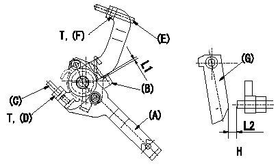
M-CSD adjustment
1. Fixing the M-CSD
(1)At roller holder advance angle a adjust the lever shaft ball pin so that it contacts the roller holder.
(2)At this time, adjust the position of the M-CSD lever (A) using adjusting screw (C) so that the clearance between the M-CSD lever (A) and the stopper (B) becomes L1. Then fix using nut (D).
TT
2. M-FICD adjustment
(1)Move the CSD lever (A) through its full stroke.
(2)Adjust screw (E) so that the control lever (G)'s position is b (the clearance between the control lever and the idling set screw is L2). Then fix using the nut (F).
TT
Pump speed NE
H = from idle to position b
----------
L1=0.5+2mm L2=4.8+-1mm a=0deg b=7deg T=6~9N-m(0.6~0.9kgf-m)
----------
L1=0.5+2mm L2=4.8+-1mm T=6~9N-m(0.6~0.9kgf-m) b=7deg
----------
L1=0.5+2mm L2=4.8+-1mm a=0deg b=7deg T=6~9N-m(0.6~0.9kgf-m)
----------
L1=0.5+2mm L2=4.8+-1mm T=6~9N-m(0.6~0.9kgf-m) b=7deg