Rating:
Information injection-pump assembly
ZEXEL
104747-7020
1047477020
KOMATSU
6272711120
6272711120
Compare Prices: .
As an associate, we earn commssions on qualifying purchases through the links below

Diesel Fuel Injection Pump 104646-7020 6272-71-1120 Compatible for ZEXEL
BsapP High quality products are durable || Plug and play, no splicing or cutting, simple and convenient installation || Made of high quality materials, it is resistant to high temperature, wear and corrosion || Precision work, high precision, stable performance, low oil consumption and long service life || Diesel Fuel Injection Pump 104646-7020 6272-71-1120 Compatible for ZEXEL
BsapP High quality products are durable || Plug and play, no splicing or cutting, simple and convenient installation || Made of high quality materials, it is resistant to high temperature, wear and corrosion || Precision work, high precision, stable performance, low oil consumption and long service life || Diesel Fuel Injection Pump 104646-7020 6272-71-1120 Compatible for ZEXEL

$1,330.00
19 Sep 2022
0.0022[0.00] Pounds
CN: SFGU SHOP
ReadJade Fuel Pump Compatible with: ZEXEL Fuel Injection Pump 104646-7020 104747-7020 Diesel Fuel Pump 6272-71-1120 Replacement Parts
ReadJade Compatible with: ZEXEL Fuel Injection Pump 104646-7020 104747-7020 || diesel fuel pump 6272-71-1120 || Material Type: Stainless Steel
ReadJade Compatible with: ZEXEL Fuel Injection Pump 104646-7020 104747-7020 || diesel fuel pump 6272-71-1120 || Material Type: Stainless Steel
Cross reference number
ZEXEL
104747-7020
1047477020
KOMATSU
6272711120
6272711120
Zexel num
Bosch num
Firm num
Name
104747-7020
6272711120 KOMATSU
INJECTION-PUMP ASSEMBLY
P161/CUMM
P161/CUMM
Calibration Data:
Adjustment conditions
Test oil
1404 Test oil ISO4113orSAEJ967d
1404 Test oil ISO4113orSAEJ967d
Test oil temperature
degC
45
45
50
Nozzle
105780-0060
Bosch type code
NP-DN0SD1510
Nozzle holder
105780-2150
Opening pressure
MPa
13
13
13.3
Opening pressure
kgf/cm2
133
133
136
Injection pipe
157805-7320
Injection pipe
Inside diameter - outside diameter - length (mm) mm 2-6-450
Inside diameter - outside diameter - length (mm) mm 2-6-450
Joint assembly
157641-4720
Tube assembly
157641-4020
Transfer pump pressure
kPa
20
20
20
Transfer pump pressure
kgf/cm2
0.2
0.2
0.2
Direction of rotation (viewed from drive side)
Right R
Right R
Injection timing adjustment
Pump speed
r/min
900
900
900
Average injection quantity
mm3/st.
56.2
55.7
56.7
Difference in delivery
mm3/st.
4.5
Basic
*
Oil temperature
degC
50
48
52
Injection timing adjustment_02
Pump speed
r/min
500
500
500
Average injection quantity
mm3/st.
52.3
47.8
56.8
Oil temperature
degC
48
46
50
Injection timing adjustment_03
Pump speed
r/min
800
800
800
Average injection quantity
mm3/st.
57.5
53.5
61.5
Oil temperature
degC
50
48
52
Injection timing adjustment_04
Pump speed
r/min
900
900
900
Average injection quantity
mm3/st.
56.2
54.7
57.7
Difference in delivery
mm3/st.
5
Basic
*
Oil temperature
degC
50
48
52
Injection timing adjustment_05
Pump speed
r/min
1100
1100
1100
Average injection quantity
mm3/st.
51.5
47.5
55.5
Oil temperature
degC
50
48
52
Injection quantity adjustment
Pump speed
r/min
1225
1225
1225
Average injection quantity
mm3/st.
11.9
8.9
14.9
Difference in delivery
mm3/st.
3.5
Basic
*
Oil temperature
degC
50
48
52
Injection quantity adjustment_02
Pump speed
r/min
1400
1400
1400
Average injection quantity
mm3/st.
3
Oil temperature
degC
50
48
52
Injection quantity adjustment_03
Pump speed
r/min
1225
1225
1225
Average injection quantity
mm3/st.
11.9
7.4
16.4
Basic
*
Oil temperature
degC
50
48
52
Governor adjustment
Pump speed
r/min
400
400
400
Average injection quantity
mm3/st.
8.6
6.6
10.6
Difference in delivery
mm3/st.
2
Basic
*
Oil temperature
degC
48
46
50
Governor adjustment_02
Pump speed
r/min
400
400
400
Average injection quantity
mm3/st.
8.6
6.1
11.1
Difference in delivery
mm3/st.
2.5
Basic
*
Oil temperature
degC
48
46
50
Timer adjustment
Pump speed
r/min
100
100
100
Average injection quantity
mm3/st.
80
75
85
Basic
*
Oil temperature
degC
48
46
50
Remarks
IDLE
IDLE
Timer adjustment_02
Pump speed
r/min
100
100
100
Average injection quantity
mm3/st.
80
75
85
Oil temperature
degC
48
46
50
Remarks
IDLE
IDLE
Speed control lever angle
Pump speed
r/min
400
400
400
Average injection quantity
mm3/st.
0
0
0
Oil temperature
degC
48
46
50
Remarks
Magnet OFF at idling position
Magnet OFF at idling position
0000000901
Pump speed
r/min
1100
1100
1100
Overflow quantity
cm3/min
400
270
530
Oil temperature
degC
50
48
52
Stop lever angle
Pump speed
r/min
1100
1100
1100
Pressure
kPa
500
480
520
Pressure
kgf/cm2
5.1
4.9
5.3
Basic
*
Oil temperature
degC
50
48
52
Stop lever angle_02
Pump speed
r/min
700
700
700
Pressure
kPa
392
343
441
Pressure
kgf/cm2
4
3.5
4.5
Oil temperature
degC
50
48
52
Stop lever angle_03
Pump speed
r/min
800
800
800
Pressure
kPa
422
373
471
Pressure
kgf/cm2
4.3
3.8
4.8
Oil temperature
degC
50
48
52
Stop lever angle_04
Pump speed
r/min
1100
1100
1100
Pressure
kPa
500
471
529
Pressure
kgf/cm2
5.1
4.8
5.4
Basic
*
Oil temperature
degC
50
48
52
0000001101
Pump speed
r/min
1100
1100
1100
Timer stroke
mm
2.8
2.6
3
Basic
*
Oil temperature
degC
50
48
52
_02
Pump speed
r/min
800
800
800
Timer stroke
mm
1.1
0.6
1.6
Oil temperature
degC
50
48
52
_03
Pump speed
r/min
1100
1100
1100
Timer stroke
mm
2.8
2.5
3.1
Basic
*
Oil temperature
degC
50
48
52
0000001201
Max. applied voltage
V
8
8
8
Test voltage
V
13
12
14
0000001401
Pump speed
r/min
1100
1100
1100
Average injection quantity
mm3/st.
40
39
41
Timer stroke TA
mm
2
1.8
2.2
Timer stroke variation dT
mm
0.8
0.8
0.8
Basic
*
Oil temperature
degC
50
48
52
_02
Pump speed
r/min
1100
1100
1100
Average injection quantity
mm3/st.
40
38.5
41.5
Timer stroke TA
mm
2
1.7
2.3
Timer stroke variation dT
mm
0.8
0.8
0.8
Basic
*
Oil temperature
degC
50
48
52
_03
Pump speed
r/min
1100
1100
1100
Average injection quantity
mm3/st.
30
28
32
Timer stroke TA
mm
1.1
0.6
1.6
Timer stroke variation dT
mm
1.7
1.7
1.7
Oil temperature
degC
50
48
52
Timing setting
K dimension
mm
3.3
3.2
3.4
KF dimension
mm
5.8
5.7
5.9
MS dimension
mm
2
1.9
2.1
Control lever angle alpha
deg.
16
12
20
Control lever angle beta
deg.
30
25
35
Test data Ex:
0000001801 W-CSD ADJUSTMENT
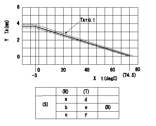
Adjustment of the W-CSD
Adjustment of the timer advance angle
1. Determine the timer advance angle using the graph (graph TA).
X:Temperature t (deg C)
Y:Timer stroke TA (mm)
(S) Cold advance
(R) Cooling water temperature (deg C)
(T) Timer piston stroke (mm)
(B) Standard point
----------
TA=-0.053t+3.881 -3degC<=t<=20degC TA=-0.0517t+3.854 20degC<=t
----------
a=76.5++degC b=20degC c=-3degC d=0mm e=2.82+-0.4mm f=4.04+-0.6mm
----------
TA=-0.053t+3.881 -3degC<=t<=20degC TA=-0.0517t+3.854 20degC<=t
----------
a=76.5++degC b=20degC c=-3degC d=0mm e=2.82+-0.4mm f=4.04+-0.6mm
0000001901 STARTING I/Q ADJUSTMENT
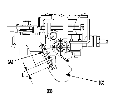
Starting Q decrease lever adjustment
Adjust using the screw (A) so that the standards are satisfied, then fix using the nut (B).
Screw (A) protrusion: L
(B) Nut (SW10, T1 after completing adjustment)
(C) Stop lever
----------
L=7.4~11.1mm T1=6~9N-m(0.6~0.9kgf-m)
----------
L=7.4~11.1mm
----------
L=7.4~11.1mm T1=6~9N-m(0.6~0.9kgf-m)
----------
L=7.4~11.1mm
0000002001 TAMPER PROOF
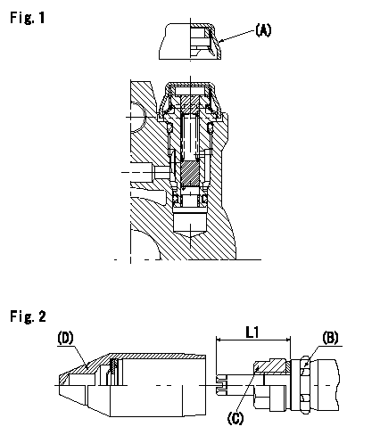
Tamperproof installation procedure
A:Cap
B:Rubber vibration damper
C:Nut
D:Cap
L1:Inspection dimension
Fig. 1 Regulating valve seal
1) Insert the cap A horizontally (press fit).
2) After insertion (press-fitting), tighten the cap to torque T1, and confirm that it is not pulled out at load F1.
Fig.2 Full load adjusting screw
1) Confirm the position of the rubber vibration damper (B) and then tighten nut (C) to the torque T2.
----------
L1=23~28mm F1=49N(5kgf) T1=4.9N-m(0.5kgf-m) T2=7~9N-m(0.7~0.9kgf-m)
----------
L1=23~28mm
----------
L1=23~28mm F1=49N(5kgf) T1=4.9N-m(0.5kgf-m) T2=7~9N-m(0.7~0.9kgf-m)
----------
L1=23~28mm
Have questions with 104747-7020?
Group cross 104747-7020 ZEXEL
Komatsu
104747-7020
6272711120
INJECTION-PUMP ASSEMBLY
P161/CUMM
P161/CUMM