Rating:
Information injection-pump assembly
ZEXEL
104746-5450
1047465450
ISUZU
8973503950
8973503950
Cross reference number
ZEXEL
104746-5450
1047465450
ISUZU
8973503950
8973503950
Zexel num
Bosch num
Firm num
Name
Calibration Data:
Adjustment conditions
Test oil
1404 Test oil ISO4113orSAEJ967d
1404 Test oil ISO4113orSAEJ967d
Test oil temperature
degC
45
45
50
Nozzle
105780-0060
Bosch type code
NP-DN0SD1510
Nozzle holder
105780-2150
Opening pressure
MPa
13
13
13.3
Opening pressure
kgf/cm2
133
133
136
Injection pipe
157805-7320
Injection pipe
Inside diameter - outside diameter - length (mm) mm 2-6-450
Inside diameter - outside diameter - length (mm) mm 2-6-450
Joint assembly
157641-4720
Tube assembly
157641-4020
Transfer pump pressure
kPa
20
20
20
Transfer pump pressure
kgf/cm2
0.2
0.2
0.2
Direction of rotation (viewed from drive side)
Left L
Left L
(Solenoid timer adjustment condition)
OFF
Timer measuring device installation position
Low pressure side LOW PRESSURE SIDE
Low pressure side LOW PRESSURE SIDE
Injection timing adjustment
Pump speed
r/min
1100
1100
1100
Average injection quantity
mm3/st.
72.7
72.2
73.2
Difference in delivery
mm3/st.
6
Basic
*
Oil temperature
degC
50
48
52
Injection timing adjustment_02
Pump speed
r/min
500
500
500
Average injection quantity
mm3/st.
54.8
49.3
60.3
Oil temperature
degC
48
46
50
Injection timing adjustment_03
Pump speed
r/min
750
750
750
Average injection quantity
mm3/st.
64.5
59
70
Oil temperature
degC
50
48
52
Injection timing adjustment_04
Pump speed
r/min
900
900
900
Average injection quantity
mm3/st.
71.4
65.9
76.9
Oil temperature
degC
50
48
52
Injection timing adjustment_05
Pump speed
r/min
1100
1100
1100
Average injection quantity
mm3/st.
72.7
71.7
73.7
Difference in delivery
mm3/st.
6
Basic
*
Oil temperature
degC
50
48
52
Injection timing adjustment_06
Pump speed
r/min
1900
1900
1900
Average injection quantity
mm3/st.
83.9
79.4
88.4
Oil temperature
degC
50
48
52
Injection quantity adjustment
Pump speed
r/min
2350
2350
2350
Average injection quantity
mm3/st.
28.4
25.4
31.4
Difference in delivery
mm3/st.
4
Basic
*
Oil temperature
degC
52
50
54
Injection quantity adjustment_02
Pump speed
r/min
2600
2600
2600
Average injection quantity
mm3/st.
5
Oil temperature
degC
55
52
58
Injection quantity adjustment_03
Pump speed
r/min
2350
2350
2350
Average injection quantity
mm3/st.
28.4
25.4
31.4
Difference in delivery
mm3/st.
4
Basic
*
Oil temperature
degC
52
50
54
Governor adjustment
Pump speed
r/min
365
365
365
Average injection quantity
mm3/st.
10.6
8.6
12.6
Difference in delivery
mm3/st.
2
Basic
*
Oil temperature
degC
48
46
50
Governor adjustment_02
Pump speed
r/min
365
365
365
Average injection quantity
mm3/st.
10.6
8.6
12.6
Difference in delivery
mm3/st.
2
Basic
*
Oil temperature
degC
48
46
50
Timer adjustment
Pump speed
r/min
100
100
100
Average injection quantity
mm3/st.
90
70
110
Basic
*
Oil temperature
degC
48
46
50
Remarks
Full
Full
Timer adjustment_02
Pump speed
r/min
100
100
100
Average injection quantity
mm3/st.
90
70
110
Oil temperature
degC
48
46
50
Remarks
Full
Full
Speed control lever angle
Pump speed
r/min
365
365
365
Average injection quantity
mm3/st.
0
0
0
Oil temperature
degC
48
46
50
Remarks
Magnet OFF at idling position
Magnet OFF at idling position
0000000901
Pump speed
r/min
1600
1600
1600
Overflow quantity with S/T ON
cm3/min
1120
890
1350
Oil temperature
degC
50
48
52
Stop lever angle
Pump speed
r/min
1600
1600
1600
Pressure with S/T ON
kPa
667
628
706
Pressure with S/T ON
kgf/cm2
6.8
6.4
7.2
Pressure with S/T OFF
kPa
598
578
618
Pressure with S/T OFF
kgf/cm2
6.1
5.9
6.3
Basic
*
Oil temperature
degC
50
48
52
Remarks
OFF
OFF
Stop lever angle_02
Pump speed
r/min
1300
1300
1300
Pressure with S/T ON
kPa
569
520
618
Pressure with S/T ON
kgf/cm2
5.8
5.3
6.3
Oil temperature
degC
50
48
52
Stop lever angle_03
Pump speed
r/min
1500
1500
1500
Pressure with S/T OFF
kPa
569
540
598
Pressure with S/T OFF
kgf/cm2
5.8
5.5
6.1
Oil temperature
degC
50
48
52
Stop lever angle_04
Pump speed
r/min
1600
1600
1600
Pressure with S/T ON
kPa
667
628
706
Pressure with S/T ON
kgf/cm2
6.8
6.4
7.2
Pressure with S/T OFF
kPa
598
578
618
Pressure with S/T OFF
kgf/cm2
6.1
5.9
6.3
Basic
*
Oil temperature
degC
50
48
52
Remarks
OFF
OFF
Stop lever angle_05
Pump speed
r/min
1900
1900
1900
Pressure with S/T OFF
kPa
696
667
725
Pressure with S/T OFF
kgf/cm2
7.1
6.8
7.4
Oil temperature
degC
50
48
52
Stop lever angle_06
Pump speed
r/min
2200
2200
2200
Pressure with S/T OFF
kPa
824
765
883
Pressure with S/T OFF
kgf/cm2
8.4
7.8
9
Oil temperature
degC
52
50
54
0000001101
Pump speed
r/min
1600
1600
1600
Timer stroke with S/T ON
mm
4.1
3.7
4.5
Timer stroke with S/T OFF
mm
2.5
2.3
2.7
Basic
*
Oil temperature
degC
50
48
52
Remarks
OFF
OFF
_02
Pump speed
r/min
1300
1300
1300
Timer stroke with S/T ON
mm
1.7
1.2
2.2
Oil temperature
degC
50
48
52
_03
Pump speed
r/min
1600
1600
1600
Timer stroke with S/T ON
mm
4.1
3.6
4.6
Timer stroke with S/T OFF
mm
2.5
2.3
2.7
Basic
*
Oil temperature
degC
50
48
52
Remarks
OFF
OFF
_04
Pump speed
r/min
1800
1800
1800
Timer stroke with S/T OFF
mm
4.1
3.7
4.5
Oil temperature
degC
50
48
52
_05
Pump speed
r/min
2200
2200
2200
Timer stroke with S/T OFF
mm
4.8
4.5
5.2
Oil temperature
degC
52
50
54
0000001201
Max. applied voltage
V
8
8
8
Test voltage
V
13
12
14
Timing setting
K dimension
mm
3.6
3.5
3.7
KF dimension
mm
7.7
7.6
7.8
MS dimension
mm
0.8
0.7
0.9
Pre-stroke
mm
0.2
0.18
0.22
Control lever angle alpha
deg.
18
14
22
Control lever angle beta
deg.
37
32
42
Test data Ex:
0000001801 POTENTIOMETER ADJUSTMENT
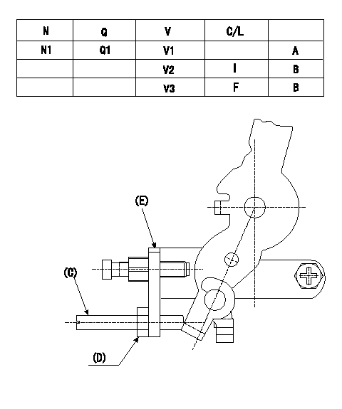
Adjusting method (applied voltage Vi, dummy bolt method)
1. Hold the dummy bolt against the control lever at position N = N1 and Q = Q1 and fix using the lock nut.
2. At potentiometer adjustment, with the control lever contacting the dummy bolt, adjust the potentiometer so that the output voltage is V1.
3. After completing adjustment remove the dummy bolt. Confirm that the potentiometer output voltage is as specified above at the control lever idle position and full position.
N:Pump speed
Q:Injection quantity
V:Output voltage
A:Adjusting point
B:Checking point
I:Idle
F:Full speed
(C) Corresponding to dummy bolt 146526-3300
(D) Corresponding to nut 013020-6040
(E) Dummy bolt installation bracket
----------
N1=1420r/min Q1=26.2+-1.0mm3/st V1=4.33+-0.03V Vi=10V
----------
N1=1420r/min Q1=26.2+-1.0mm3/st V1=4.33+-0.03V V2=(1.53+-0.61V) V3=7.70+-0.72V
----------
N1=1420r/min Q1=26.2+-1.0mm3/st V1=4.33+-0.03V Vi=10V
----------
N1=1420r/min Q1=26.2+-1.0mm3/st V1=4.33+-0.03V V2=(1.53+-0.61V) V3=7.70+-0.72V
0000001901 V-FICD ADJUSTMENT
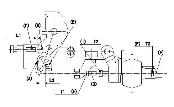
Adjustment of the V-FICD
1. Mount the V-FICD after the completion of potentiometer adjustment.
2. Confirm that the clearance between the control lever (B) and the actuator rod (A) is at least L2.
3. Insert the L1 shim between the control lever (D) and the idle set screw (C).
4. Adjust the stroke adjusting screw (E) so that the actuator moves through its full stroke, then fix using nut (F).
Note
When adjustment is not possible using the stroke adjusting screw (E), move the actuator rod position using (G), (H) and (I). Then, readjust the stroke using (E) and (F).
5. Apply negative pressure P1 to the actuator and confirm the full stroke.
6. After releasing negative pressure, re-confirm that the clearance between (A) and (B) is at least L2.
----------
L1=0.7+-0.1mm L2=1.0mm P1=-53.3kPa(-400mmHg)
----------
L1=0.7+-0.1mm L2=1.0++mm T1=1.4~2.0Nm(0.14~0.20kgfm) T2=3.4~4.9Nm(0.35~0.50kgfm)
----------
L1=0.7+-0.1mm L2=1.0mm P1=-53.3kPa(-400mmHg)
----------
L1=0.7+-0.1mm L2=1.0++mm T1=1.4~2.0Nm(0.14~0.20kgfm) T2=3.4~4.9Nm(0.35~0.50kgfm)