
Rating:
Information injection-pump assembly
ZEXEL
104745-0121
1047450121
MAZDA
W90313800A
w90313800a
Cross reference number
ZEXEL
104745-0121
1047450121
MAZDA
W90313800A
w90313800a
Zexel num
Bosch num
Firm num
Name
Calibration Data:
Adjustment conditions
Test oil
1404 Test oil ISO4113orSAEJ967d
1404 Test oil ISO4113orSAEJ967d
Test oil temperature
degC
45
45
50
Nozzle
105780-0060
Bosch type code
NP-DN0SD1510
Nozzle holder
105780-2150
Opening pressure
MPa
13
13
13.3
Opening pressure
kgf/cm2
133
133
136
Injection pipe
157805-7320
Injection pipe
Inside diameter - outside diameter - length (mm) mm 2-6-450
Inside diameter - outside diameter - length (mm) mm 2-6-450
Joint assembly
157641-4720
Tube assembly
157641-4020
Transfer pump pressure
kPa
20
20
20
Transfer pump pressure
kgf/cm2
0.2
0.2
0.2
Direction of rotation (viewed from drive side)
Left L
Left L
Injection timing adjustment
Pump speed
r/min
1250
1250
1250
Average injection quantity
mm3/st.
56.8
56.3
57.3
Difference in delivery
mm3/st.
4.5
Basic
*
Oil temperature
degC
50
48
52
Injection timing adjustment_02
Pump speed
r/min
500
500
500
Average injection quantity
mm3/st.
51.5
48.5
54.5
Oil temperature
degC
48
46
50
Injection timing adjustment_03
Pump speed
r/min
1250
1250
1250
Average injection quantity
mm3/st.
56.8
55.8
57.8
Difference in delivery
mm3/st.
5
Basic
*
Oil temperature
degC
50
48
52
Injection timing adjustment_04
Pump speed
r/min
2000
2000
2000
Average injection quantity
mm3/st.
56.2
52.7
59.7
Oil temperature
degC
50
48
52
Injection quantity adjustment
Pump speed
r/min
2450
2450
2450
Average injection quantity
mm3/st.
22.9
19.9
25.9
Difference in delivery
mm3/st.
4.5
Basic
*
Oil temperature
degC
55
52
58
Injection quantity adjustment_02
Pump speed
r/min
2700
2700
2700
Average injection quantity
mm3/st.
8
Oil temperature
degC
55
52
58
Injection quantity adjustment_03
Pump speed
r/min
2450
2450
2450
Average injection quantity
mm3/st.
22.9
12.9
32.9
Difference in delivery
mm3/st.
5
Basic
*
Oil temperature
degC
55
52
58
Governor adjustment
Pump speed
r/min
360
360
360
Average injection quantity
mm3/st.
10.8
9.8
11.8
Difference in delivery
mm3/st.
1.7
Basic
*
Oil temperature
degC
48
46
50
Governor adjustment_02
Pump speed
r/min
360
360
360
Average injection quantity
mm3/st.
10.8
9.3
12.3
Difference in delivery
mm3/st.
2.2
Basic
*
Oil temperature
degC
48
46
50
Boost compensator adjustment
Pump speed
r/min
400
400
400
Average injection quantity
mm3/st.
17
15
19
Difference in delivery
mm3/st.
3
Oil temperature
degC
48
46
50
Timer adjustment
Pump speed
r/min
150
150
150
Average injection quantity
mm3/st.
70
55
90
Basic
*
Oil temperature
degC
48
46
50
Remarks
Full
Full
Timer adjustment_02
Pump speed
r/min
150
150
150
Average injection quantity
mm3/st.
70
50
90
Oil temperature
degC
48
46
50
Remarks
Full
Full
Speed control lever angle
Pump speed
r/min
360
360
360
Average injection quantity
mm3/st.
0
0
0
Oil temperature
degC
48
46
50
Remarks
Magnet OFF at idling position
Magnet OFF at idling position
0000000901
Pump speed
r/min
1250
1250
1250
Overflow quantity with S/T OFF
cm3/min
400
270
530
Oil temperature
degC
50
48
52
Stop lever angle
Pump speed
r/min
1250
1250
1250
Pressure with S/T ON
kPa
559
520
598
Pressure with S/T ON
kgf/cm2
5.7
5.3
6.1
Pressure with S/T OFF
kPa
471
442
500
Pressure with S/T OFF
kgf/cm2
4.8
4.5
5.1
Basic
*
Oil temperature
degC
50
48
52
Remarks
OFF
OFF
Stop lever angle_02
Pump speed
r/min
1250
1250
1250
Pressure with S/T OFF
kPa
471
432
510
Pressure with S/T OFF
kgf/cm2
4.8
4.4
5.2
Basic
*
Oil temperature
degC
50
48
52
Remarks
OFF
OFF
0000001101
Pump speed
r/min
1250
1250
1250
Timer stroke with S/T ON
mm
6
5.6
6.4
Timer stroke with S/T OFF
mm
3.9
3.7
4.1
Basic
*
Oil temperature
degC
50
48
52
Remarks
OFF
OFF
_02
Pump speed
r/min
500
500
500
Timer stroke with S/T ON
mm
0.9
-0.1
1.9
Oil temperature
degC
48
46
50
_03
Pump speed
r/min
1250
1250
1250
Timer stroke with S/T ON
mm
6
5.4
6.6
Timer stroke with S/T OFF
mm
3.9
3.5
4.3
Basic
*
Oil temperature
degC
50
48
52
Remarks
OFF
OFF
_04
Pump speed
r/min
1750
1750
1750
Timer stroke with S/T ON
mm
8.9
7.9
9.9
Timer stroke with S/T OFF
mm
7
6.2
7.8
Oil temperature
degC
50
48
52
_05
Pump speed
r/min
2100
2100
2100
Timer stroke with S/T ON
mm
9.8
8.8
10.6
Oil temperature
degC
52
50
54
0000001201
Max. applied voltage
V
8
8
8
Test voltage
V
13
12
14
0000001401
Pump speed
r/min
1250
1250
1250
Average injection quantity
mm3/st.
44
43.5
44.5
Timer stroke TA
mm
3.4
3.4
3.4
Timer stroke variation dT
mm
0.5
0.3
0.7
Basic
*
Oil temperature
degC
50
48
52
Remarks
OFF
OFF
_02
Pump speed
r/min
1250
1250
1250
Average injection quantity
mm3/st.
44
43
45
Timer stroke TA
mm
3.4
3.4
3.4
Timer stroke variation dT
mm
0.5
0.1
0.9
Basic
*
Oil temperature
degC
50
48
52
Remarks
OFF
OFF
_03
Pump speed
r/min
1250
1250
1250
Average injection quantity
mm3/st.
41
39.5
42.5
Timer stroke TA
mm
2.6
2.6
2.6
Timer stroke variation dT
mm
1.3
0.7
1.9
Oil temperature
degC
50
48
52
Timing setting
K dimension
mm
3.3
3.2
3.4
KF dimension
mm
6.01
5.91
6.11
MS dimension
mm
0.9
0.8
1
Pre-stroke
mm
0.03
0.01
0.05
Control lever angle alpha
deg.
12.5
8.5
16.5
Control lever angle beta
deg.
40
37
43
Test data Ex:
0000001801 CONTROL STANDARD AT IDLING
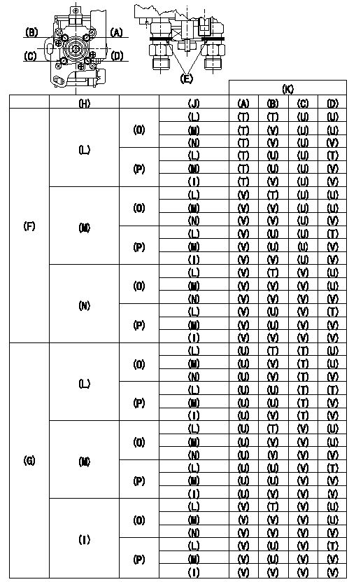
Standards for idle difference in delivery control
After idle adjustment, measure the idle injection quantities of (A) to (D).
Install the colored rings to the delivery valve holders (A) to (D) in accordance with the table.
(A): A cylinder (B) :B cylinder (C) : C cylinder (D): D cylinder
(E): Collar ring
(F): (A) >= (C)
(G): (C) > (A)
(H): (A) - (C) or (C) - (A)
(I): 0.2, 0.1(mm3/st)
(J): (B) - (D) or (D) - (B)
(K): Ring color
(L): At least 0.6 mm3/st
(M): 0.3, 0.4, 0.5 (mm3/st)
(N): 0.2, 0.1, 0.0 (mm3/st)
(O): (B) >= (D)
(P): (D) > (B)
(T): Yellow
(U): White
(V): Red
----------
----------
----------
----------
0000001901 POTENTIOMETER ADJUSTMENT
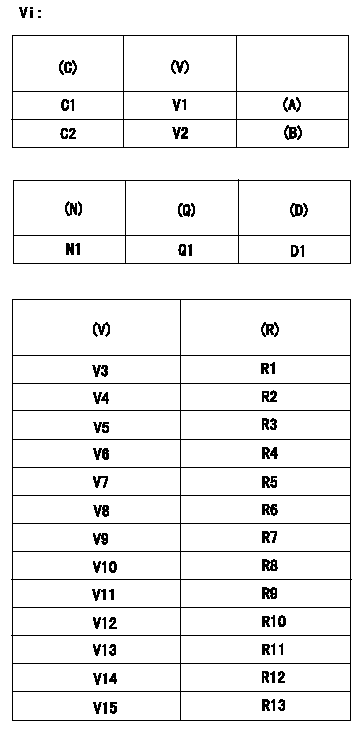
Adjustment of the potentiometer
Vi = input applied voltage
(1)Potentiometer setting:
(A): Adjusting point
(B): Checking point
(C): Control lever opening
(V): P/N output voltage
(2)Dummy bolt setting:
At pump speed N1, fix the control lever using the dummy bolt so that the injection quantity = Q1 in the table below.
(N): Speed of the pump
(Q): Injection quantity
(D): Targeted lever angle
C1:Full speed position
C2:Idling position
(3)Read the output voltage (V) of the potentiometer in the state indicated in (2) above. Then, select the compensation resistor from the following table and replace.
(R): Compensation resistance
Note
As the output voltage is compensated in the control unit after replacing the compensation resistor, confirmation is not necessary.
----------
N1=1,000r/min Q1=25.8+-1.0mm3/1,000st
----------
Vi=10V V1=8.40+-0.03V V2=1.73+-0.70V N1=1,000r/min Q1=25.8+-1.0cm3/1000st D1=13.6deg V3=3.22~3.33V V4=3.34~3.45V V5=3.46~3.57V V6=3.58~3.69V V7=3.70~3.81V V8=3.82~3.93V V9=3.94~4.05V V10=4.06~4.17V V11=4.18~4.29V V12=4.30~4.41V V13=4.42~4.53V V14=4.51~4.65V V15=4.66~4.77V R1=No.1,0.18kohm R2=No.2,0.3kohm R3=No.3,0.43kohm R4=No.4,0.62kohm R5=No.5,0.82kohm R6=No.6,1.1kohm R7=No.7,1.5kohm R8=No.8,2kohm R9=No.9,2.7kohm R10=No.10,3.9kohm R11=No.11,5.6kohm R12=No.12,8.2kohm R13=No.13,15kohm
----------
N1=1,000r/min Q1=25.8+-1.0mm3/1,000st
----------
Vi=10V V1=8.40+-0.03V V2=1.73+-0.70V N1=1,000r/min Q1=25.8+-1.0cm3/1000st D1=13.6deg V3=3.22~3.33V V4=3.34~3.45V V5=3.46~3.57V V6=3.58~3.69V V7=3.70~3.81V V8=3.82~3.93V V9=3.94~4.05V V10=4.06~4.17V V11=4.18~4.29V V12=4.30~4.41V V13=4.42~4.53V V14=4.51~4.65V V15=4.66~4.77V R1=No.1,0.18kohm R2=No.2,0.3kohm R3=No.3,0.43kohm R4=No.4,0.62kohm R5=No.5,0.82kohm R6=No.6,1.1kohm R7=No.7,1.5kohm R8=No.8,2kohm R9=No.9,2.7kohm R10=No.10,3.9kohm R11=No.11,5.6kohm R12=No.12,8.2kohm R13=No.13,15kohm
0000002001 A/T PLATE ADJUSTMENT
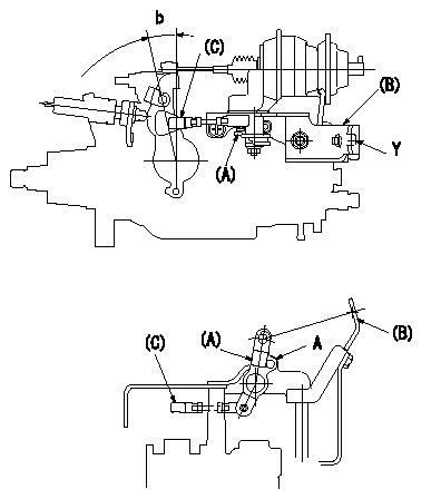
(1)A/T link lever initial position setting
With the control lever at position a, adjust the length of connecting rod (C) so that the pin D1 can pass through the A/T link lever (A) and the bracket (B) at A. Then fix.
Tightening torque T1
(2)A/T wire stroke adjustment (at control lever idle to full positions)
Attach the A/T wire stroke measuring device to bracket (B) at position Y and confirm that the stroke is L1.
If the stroke is not as specified, replace the A/T link lever (A) and reconfirm the stroke.
----------
a=0deg D1=Dia.5.8-0.2mm L2=30+-3mm T1=2.5~2.9N-m(0.25~0.31kgf-m) L1=30+-2mm
----------
b=(12.5deg)
----------
a=0deg D1=Dia.5.8-0.2mm L2=30+-3mm T1=2.5~2.9N-m(0.25~0.31kgf-m) L1=30+-2mm
----------
b=(12.5deg)
0000002101 WIRE
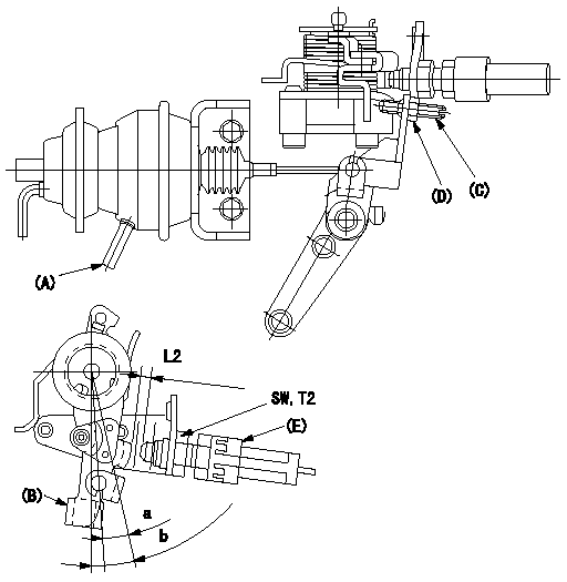
Confirmation of the wire length:
Accelerator wire: Idle-full stroke: L1
Adjustment of the double stage actuator:
(1)Apply negative pressure P1 {P2} to the actuator through the negative pressure inlet port (A).
(2)In status (1) above, adjust screw (C) so that the control lever (B)'s position is a [ie, the gap between the control lever and the idle switch (E) is L2]. Fix using the nut (D). Torque (D) to T1.
(3)Idle switch (E)'s locknut tightening torque is T2.
b:Alpha
----------
L1=34.1+3.5-5.5mm L2=5.1+-0.5mm a=9deg P1=-66.6kPa P2=-500mmHg T1=6~9N-m(0.6~0.9kgf-m) T2=12~15N-m(1.2~1.5kgf-m)
----------
a=9deg b=12.5+-4deg L2=5.1+-0.5mm SW=SW17 T2=12~15N-m(1.2~1.5kgf-m)
----------
L1=34.1+3.5-5.5mm L2=5.1+-0.5mm a=9deg P1=-66.6kPa P2=-500mmHg T1=6~9N-m(0.6~0.9kgf-m) T2=12~15N-m(1.2~1.5kgf-m)
----------
a=9deg b=12.5+-4deg L2=5.1+-0.5mm SW=SW17 T2=12~15N-m(1.2~1.5kgf-m)