Rating:
Information injection-pump assembly
ZEXEL
104742-7300
1047427300
Cross reference number
ZEXEL
104742-7300
1047427300
Zexel num
Bosch num
Firm num
Name
104742-7300
INJECTION-PUMP ASSEMBLY
Calibration Data:
Adjustment conditions
Test oil
1404 Test oil ISO4113orSAEJ967d
1404 Test oil ISO4113orSAEJ967d
Test oil temperature
degC
45
45
50
Nozzle
105780-0060
Bosch type code
NP-DN0SD1510
Nozzle holder
105780-2150
Opening pressure
MPa
13
13
13.3
Opening pressure
kgf/cm2
133
133
136
Injection pipe
157805-7320
Injection pipe
Inside diameter - outside diameter - length (mm) mm 2-6-450
Inside diameter - outside diameter - length (mm) mm 2-6-450
Joint assembly
157641-4720
Tube assembly
157641-4020
Transfer pump pressure
kPa
20
20
20
Transfer pump pressure
kgf/cm2
0.2
0.2
0.2
Direction of rotation (viewed from drive side)
Right R
Right R
Injection timing adjustment
Pump speed
r/min
1600
1600
1600
Average injection quantity
mm3/st.
66.2
65.7
66.7
Difference in delivery
mm3/st.
6
Basic
*
Oil temperature
degC
50
48
52
Injection timing adjustment_02
Pump speed
r/min
500
500
500
Average injection quantity
mm3/st.
55.8
51.3
60.3
Oil temperature
degC
48
46
50
Injection timing adjustment_03
Pump speed
r/min
600
600
600
Average injection quantity
mm3/st.
52
47.5
56.5
Oil temperature
degC
50
48
52
Injection timing adjustment_04
Pump speed
r/min
900
900
900
Average injection quantity
mm3/st.
53.9
49.4
58.4
Oil temperature
degC
50
48
52
Injection timing adjustment_05
Pump speed
r/min
1350
1350
1350
Average injection quantity
mm3/st.
65
60.5
69.5
Oil temperature
degC
50
48
52
Injection timing adjustment_06
Pump speed
r/min
1600
1600
1600
Average injection quantity
mm3/st.
66.2
65.2
67.2
Difference in delivery
mm3/st.
6
Basic
*
Oil temperature
degC
50
48
52
Injection timing adjustment_07
Pump speed
r/min
1800
1800
1800
Average injection quantity
mm3/st.
64.3
60.3
68.3
Oil temperature
degC
50
48
52
Injection quantity adjustment
Pump speed
r/min
2050
2050
2050
Average injection quantity
mm3/st.
5.2
2.2
8.2
Difference in delivery
mm3/st.
3
Basic
*
Oil temperature
degC
52
50
54
Injection quantity adjustment_02
Pump speed
r/min
2100
2100
2100
Average injection quantity
mm3/st.
5
Oil temperature
degC
52
50
54
Injection quantity adjustment_03
Pump speed
r/min
2050
2050
2050
Average injection quantity
mm3/st.
5.2
0.7
9.7
Difference in delivery
mm3/st.
3
Basic
*
Oil temperature
degC
52
50
54
Governor adjustment
Pump speed
r/min
325
325
325
Average injection quantity
mm3/st.
16.7
14.7
18.7
Difference in delivery
mm3/st.
3
Basic
*
Oil temperature
degC
48
46
50
Governor adjustment_02
Pump speed
r/min
325
325
325
Average injection quantity
mm3/st.
16.7
14.2
19.2
Difference in delivery
mm3/st.
3
Basic
*
Oil temperature
degC
48
46
50
Timer adjustment
Pump speed
r/min
100
100
100
Average injection quantity
mm3/st.
85
65
105
Basic
*
Oil temperature
degC
48
46
50
Remarks
Full
Full
Timer adjustment_02
Pump speed
r/min
150
150
150
Average injection quantity
mm3/st.
88
68
108
Basic
*
Oil temperature
degC
48
46
50
Remarks
Full
Full
Timer adjustment_03
Pump speed
r/min
100
100
100
Average injection quantity
mm3/st.
85
65
105
Oil temperature
degC
48
46
50
Remarks
Full
Full
Speed control lever angle
Pump speed
r/min
100
100
100
Average injection quantity
mm3/st.
0
0
0
Oil temperature
degC
48
46
50
Remarks
Magnet ON at idling position and reversed operate
Magnet ON at idling position and reversed operate
Speed control lever angle_02
Pump speed
r/min
325
325
325
Average injection quantity
mm3/st.
0
0
0
Oil temperature
degC
48
46
50
Remarks
Magnet ON at idling position and reversed operate
Magnet ON at idling position and reversed operate
Speed control lever angle_03
Pump speed
r/min
100
100
100
Average injection quantity
mm3/st.
0
0
0
Oil temperature
degC
48
46
50
Remarks
Magnet OFF at idling position and stop lever operate
Magnet OFF at idling position and stop lever operate
Speed control lever angle_04
Pump speed
r/min
325
325
325
Average injection quantity
mm3/st.
0
0
0
Oil temperature
degC
48
46
50
Remarks
Magnet OFF at idling position and stop lever operate
Magnet OFF at idling position and stop lever operate
0000000901
Pump speed
r/min
1000
1000
1000
Overflow quantity
cm3/min
1350
1120
1580
Oil temperature
degC
50
48
52
Stop lever angle
Pump speed
r/min
1000
1000
1000
Pressure
kPa
490
461
519
Pressure
kgf/cm2
5
4.7
5.3
Basic
*
Oil temperature
degC
50
48
52
Stop lever angle_02
Pump speed
r/min
750
750
750
Pressure
kPa
441
402
480
Pressure
kgf/cm2
4.5
4.1
4.9
Oil temperature
degC
50
48
52
Stop lever angle_03
Pump speed
r/min
1000
1000
1000
Pressure
kPa
490
451
529
Pressure
kgf/cm2
5
4.6
5.4
Basic
*
Oil temperature
degC
50
48
52
Stop lever angle_04
Pump speed
r/min
1500
1500
1500
Pressure
kPa
608
569
647
Pressure
kgf/cm2
6.2
5.8
6.6
Oil temperature
degC
50
48
52
0000001101
Pump speed
r/min
1000
1000
1000
Timer stroke
mm
1.2
1
1.4
Basic
*
Oil temperature
degC
50
48
52
_02
Pump speed
r/min
1000
1000
1000
Timer stroke
mm
1.2
0.8
1.6
Basic
*
Oil temperature
degC
50
48
52
_03
Pump speed
r/min
1500
1500
1500
Timer stroke
mm
2.5
2
2.9
Oil temperature
degC
50
48
52
0000001201
Max. applied voltage
V
16
16
16
Test voltage
Reverse operation (At Normal: OFF, At Stop: ON) V 25 24 26
Reverse operation (At Normal: OFF, At Stop: ON) V 25 24 26
Timing setting
K dimension
mm
3.1
3
3.2
KF dimension
mm
5.5
5.4
5.6
MS dimension
mm
0.9
0.8
1
Pre-stroke
mm
0.45
0.43
0.47
Control lever angle alpha
deg.
25
21
29
Control lever angle beta
deg.
35
30
40
Test data Ex:
0000001801 Temp. adjust full-load screw
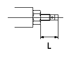
Temporary full load screw adjustment
Set the full load screw protrusion at L mm at assembly.
----------
L=14+-0.5mm
----------
L=14+-0.5mm
----------
L=14+-0.5mm
----------
L=14+-0.5mm
0000001901 STOP LEVER ADJUSTMENT
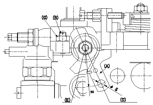
Adjustment of the stop lever
1. Confirm that the starting injection quantity is within standards at the normal position.
If below the specified lower limit, move the stop lever serrations one tooth and reconfirm.
2. Pull the stop lever (A) to the fuel cut direction at the standard idling speed of N and adjust the screw (B) to the position Q.
Fix nut (C) to the torque T at the position where the clearance between the stop lever and the end of the screw is L mm (the screw is returned 2 turns).
The head of the screw must protrude above the face of the nut. If the head of the screw is below the face of the nut, adjust the clearance between the stop lever A and the end of the screw at Q to L mm or more.
3. If adjustment in item 2 is not possible, move the stop lever installation position 1 tooth.
4. The stop lever's operating force is max. M kg (at R = 35). The stop lever must operate smoothly.
(D) Normal position
(E) Stop position
----------
N=325r/min Q=0mm3/st T=6~9N-m(0.6~0.9kgf-m) L=2mm M=4.0kg
----------
S=Dia6.5+0.09mm R=35mm
----------
N=325r/min Q=0mm3/st T=6~9N-m(0.6~0.9kgf-m) L=2mm M=4.0kg
----------
S=Dia6.5+0.09mm R=35mm
Have questions with 104742-7300?
Group cross 104742-7300 ZEXEL
104742-7300
INJECTION-PUMP ASSEMBLY