Rating:
Information injection-pump assembly
ZEXEL
104741-8121
1047418121
MITSUBISHI
ME444303
me444303
Compare Prices: .
As an associate, we earn commssions on qualifying purchases through the links below
Diesel High Pressure Fuel Pump 104641-8121, ME444303 Compatible For MITSUBISHI 4M40
IAVJPUK High precision: It can accurately control the injection amount and injection time of fuel to adapt to different engine operating conditions || Good atomization performance: atomizes fuel into small particles to improve combustion efficiency || Quick response: able to quickly perform fuel injection operations according to the instructions of the engine control unit, timely meeting the power demand of the engine || Wear resistance: It is usually made of wear-resistant materials to withstand the impact of high-pressure fuel and frequent working cycles || Diesel High Pressure Fuel Pump 104641-8121, ME444303 Compatible for MITSUBISHI 4M40
IAVJPUK High precision: It can accurately control the injection amount and injection time of fuel to adapt to different engine operating conditions || Good atomization performance: atomizes fuel into small particles to improve combustion efficiency || Quick response: able to quickly perform fuel injection operations according to the instructions of the engine control unit, timely meeting the power demand of the engine || Wear resistance: It is usually made of wear-resistant materials to withstand the impact of high-pressure fuel and frequent working cycles || Diesel High Pressure Fuel Pump 104641-8121, ME444303 Compatible for MITSUBISHI 4M40
Compatible for 306 307B C D 308C D Fuel Pump 4M40 High Pressure Diesel Pump 321-4936 ME444303 104741-8122 Excavator Parts
IAVJPUK Precise fuel injection: It can inject fuel into specific positions in the cylinder with high precision, achieving more efficient combustion || Optimize combustion efficiency: Improve the adequacy of combustion, thereby enhancing the power output and torque performance of the engine || Reduce fuel consumption: Accurately control the fuel injection quantity to effectively improve fuel economy || Reduce exhaust emissions: More precise fuel injection can reduce the amount of unburned fuel and emissions, which is beneficial for environmental protection || Compatible for 306 307B C D 308C D Fuel Pump 4M40 High Pressure Diesel Pump 321-4936 ME444303 104741-8122 Excavator Parts
IAVJPUK Precise fuel injection: It can inject fuel into specific positions in the cylinder with high precision, achieving more efficient combustion || Optimize combustion efficiency: Improve the adequacy of combustion, thereby enhancing the power output and torque performance of the engine || Reduce fuel consumption: Accurately control the fuel injection quantity to effectively improve fuel economy || Reduce exhaust emissions: More precise fuel injection can reduce the amount of unburned fuel and emissions, which is beneficial for environmental protection || Compatible for 306 307B C D 308C D Fuel Pump 4M40 High Pressure Diesel Pump 321-4936 ME444303 104741-8122 Excavator Parts
Cross reference number
ZEXEL
104741-8121
1047418121
MITSUBISHI
ME444303
me444303
Zexel num
Bosch num
Firm num
Name
Calibration Data:
Adjustment conditions
Test oil
1404 Test oil ISO4113orSAEJ967d
1404 Test oil ISO4113orSAEJ967d
Test oil temperature
degC
45
45
50
Nozzle
105780-0060
Bosch type code
NP-DN0SD1510
Nozzle holder
105780-2150
Opening pressure
MPa
13
13
13.3
Opening pressure
kgf/cm2
133
133
136
Injection pipe
157805-7320
Injection pipe
Inside diameter - outside diameter - length (mm) mm 2-6-450
Inside diameter - outside diameter - length (mm) mm 2-6-450
Joint assembly
157641-4720
Tube assembly
157641-4020
Transfer pump pressure
kPa
20
20
20
Transfer pump pressure
kgf/cm2
0.2
0.2
0.2
Direction of rotation (viewed from drive side)
Right R
Right R
Injection timing adjustment
Pump speed
r/min
900
900
900
Average injection quantity
mm3/st.
63.8
63.3
64.3
Difference in delivery
mm3/st.
5
Basic
*
Oil temperature
degC
50
48
52
Injection timing adjustment_02
Pump speed
r/min
600
600
600
Average injection quantity
mm3/st.
63.2
59.2
67.2
Oil temperature
degC
50
48
52
Injection timing adjustment_03
Pump speed
r/min
750
750
750
Average injection quantity
mm3/st.
62.6
58.6
66.6
Oil temperature
degC
50
48
52
Injection timing adjustment_04
Pump speed
r/min
900
900
900
Average injection quantity
mm3/st.
63.8
62.8
64.8
Difference in delivery
mm3/st.
5.5
Basic
*
Oil temperature
degC
50
48
52
Injection timing adjustment_05
Pump speed
r/min
1000
1000
1000
Average injection quantity
mm3/st.
64.6
62.1
67.1
Oil temperature
degC
50
48
52
Injection quantity adjustment
Pump speed
r/min
1125
1125
1125
Average injection quantity
mm3/st.
23.9
21.4
26.4
Difference in delivery
mm3/st.
7.5
Basic
*
Oil temperature
degC
50
48
52
Injection quantity adjustment_02
Pump speed
r/min
1125
1125
1125
Average injection quantity
mm3/st.
23.9
20.9
26.9
Difference in delivery
mm3/st.
8
Basic
*
Oil temperature
degC
50
48
52
Injection quantity adjustment_03
Pump speed
r/min
1250
1250
1250
Average injection quantity
mm3/st.
5
Oil temperature
degC
50
48
52
Governor adjustment
Pump speed
r/min
540
540
540
Average injection quantity
mm3/st.
19.6
17.6
21.6
Difference in delivery
mm3/st.
2
Basic
*
Oil temperature
degC
50
48
52
Governor adjustment_02
Pump speed
r/min
540
540
540
Average injection quantity
mm3/st.
19.6
17.1
22.1
Difference in delivery
mm3/st.
2.5
Basic
*
Oil temperature
degC
50
48
52
Timer adjustment
Pump speed
r/min
100
100
100
Average injection quantity
mm3/st.
95
75
145
Basic
*
Oil temperature
degC
48
46
50
Remarks
Full
Full
Timer adjustment_02
Pump speed
r/min
100
100
100
Average injection quantity
mm3/st.
95
75
145
Oil temperature
degC
48
46
50
Remarks
Full
Full
Speed control lever angle
Pump speed
r/min
540
540
540
Average injection quantity
mm3/st.
0
0
0
Oil temperature
degC
50
48
52
Remarks
Magnet OFF at idling position
Magnet OFF at idling position
0000000901
Pump speed
r/min
900
900
900
Overflow quantity
cm3/min
710
580
840
Oil temperature
degC
50
48
52
Stop lever angle
Pump speed
r/min
900
900
900
Pressure
kPa
559
539
579
Pressure
kgf/cm2
5.7
5.5
5.9
Basic
*
Oil temperature
degC
50
48
52
Stop lever angle_02
Pump speed
r/min
800
800
800
Pressure
kPa
520
471
569
Pressure
kgf/cm2
5.3
4.8
5.8
Oil temperature
degC
50
48
52
Stop lever angle_03
Pump speed
r/min
900
900
900
Pressure
kPa
559
530
588
Pressure
kgf/cm2
5.7
5.4
6
Basic
*
Oil temperature
degC
50
48
52
Stop lever angle_04
Pump speed
r/min
1000
1000
1000
Pressure
kPa
598
549
647
Pressure
kgf/cm2
6.1
5.6
6.6
Oil temperature
degC
50
48
52
0000001101
Pump speed
r/min
900
900
900
Timer stroke
mm
1.5
1.3
1.7
Basic
*
Oil temperature
degC
50
48
52
_02
Pump speed
r/min
900
900
900
Timer stroke
mm
1.5
1.1
1.9
Basic
*
Oil temperature
degC
50
48
52
_03
Pump speed
r/min
1000
1000
1000
Timer stroke
mm
2.5
1.9
3.1
Oil temperature
degC
50
48
52
_04
Pump speed
r/min
1100
1100
1100
Timer stroke
mm
2.9
2.4
3.3
Oil temperature
degC
50
48
52
0000001201
Max. applied voltage
V
16
16
16
Test voltage
V
25
24
26
Timing setting
K dimension
mm
3.3
3.2
3.4
KF dimension
mm
5.8
5.7
5.9
MS dimension
mm
2
1.9
2.1
Control lever angle alpha
deg.
57
53
61
Control lever angle beta
deg.
25
20
30
Test data Ex:
0000001801 W-CSD ADJUSTMENT

Adjustment of the W-CSD
Adjust the timer stroke
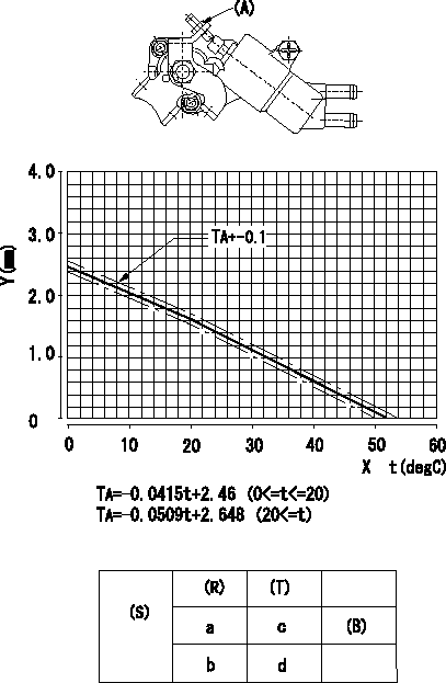
1. Adjust the timer stroke B so that it is as described in the graph. (graph TA)
2) Adjust using screw (A) to obtain the timer stroke determined in step 1.
X:Temperature t (deg C)
Y:Timer stroke TA (mm)
(S) Cold advance
(R) Cooling water temperature (deg C)
(T) Timer piston stroke (mm)
(B) Standard point
----------
----------
a=20degC b=0degC c=1.63+-4mm d=2.46+-0.6mm
----------
----------
a=20degC b=0degC c=1.63+-4mm d=2.46+-0.6mm
0000001901 TAMPER PROOF

Tamperproof installation procedure
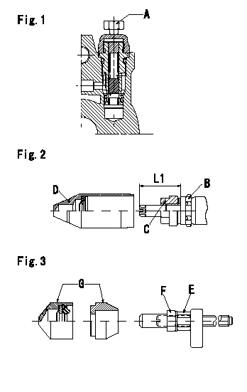
A:Position of break
B:Rubber vibration damper
C:Nut
D:Cap
E:Nut
F:Nut
G:Cap
L1:Inspection dimension
Fig. 1 Regulating valve seal
1) Target breaking torque T1
2) Maximum allowable breaking torque T2
3) Because the cap and the regulating valve are fixed using the MEC process, the bolt cannot be loosened after the bolt has been broken.
Fig.2 Full load adjusting screw
1) Confirm the position of the rubber vibration damper (B) and then tighten nut (C) to the torque T3.
Fig. 3 Maximum speed adjusting screw
1) Tighten nut (E) to the torque T4.
2) To prevent nut (E) from turning together, fix (E) using the tool, then tighten nut (F) to torque T4.
----------
L1=23~28mm T1=5~6.9N-m(0.5~0.69kgf-m) T2=9N-m(0.9kgf-m) T3=7~9N-m(0.7~0.9kgf-m) T4=6~9N-m(0.6~0.9kgf-m)
----------
L1=23~28mm
----------
L1=23~28mm T1=5~6.9N-m(0.5~0.69kgf-m) T2=9N-m(0.9kgf-m) T3=7~9N-m(0.7~0.9kgf-m) T4=6~9N-m(0.6~0.9kgf-m)
----------
L1=23~28mm

