Rating:
Information injection-pump assembly
BOSCH
9 460 613 933
9460613933
ZEXEL
104741-7111
1047417111
Cross reference number
BOSCH
9 460 613 933
9460613933
ZEXEL
104741-7111
1047417111
Zexel num
Bosch num
Firm num
Name
Calibration Data:
Adjustment conditions
Test oil
1404 Test oil ISO4113orSAEJ967d
1404 Test oil ISO4113orSAEJ967d
Test oil temperature
degC
45
45
50
Nozzle
105780-0060
Bosch type code
NP-DN0SD1510
Nozzle holder
105780-2150
Opening pressure
MPa
13
13
13.3
Opening pressure
kgf/cm2
133
133
136
Injection pipe
157805-7320
Injection pipe
Inside diameter - outside diameter - length (mm) mm 2-6-450
Inside diameter - outside diameter - length (mm) mm 2-6-450
Joint assembly
157641-4720
Tube assembly
157641-4020
Transfer pump pressure
kPa
20
20
20
Transfer pump pressure
kgf/cm2
0.2
0.2
0.2
Direction of rotation (viewed from drive side)
Right R
Right R
Injection timing adjustment
Pump speed
r/min
1000
1000
1000
Average injection quantity
mm3/st.
72.7
72.2
73.2
Difference in delivery
mm3/st.
6
Basic
*
Oil temperature
degC
50
48
52
Injection timing adjustment_02
Pump speed
r/min
400
400
400
Average injection quantity
mm3/st.
45.4
41.4
49.4
Oil temperature
degC
48
46
50
Injection timing adjustment_03
Pump speed
r/min
800
800
800
Average injection quantity
mm3/st.
70.7
66.7
74.7
Oil temperature
degC
50
48
52
Injection timing adjustment_04
Pump speed
r/min
1000
1000
1000
Average injection quantity
mm3/st.
72.7
71.7
73.7
Difference in delivery
mm3/st.
6
Basic
*
Oil temperature
degC
50
48
52
Injection timing adjustment_05
Pump speed
r/min
1300
1300
1300
Average injection quantity
mm3/st.
68
65.5
70.5
Oil temperature
degC
50
48
52
Injection quantity adjustment
Pump speed
r/min
1425
1425
1425
Average injection quantity
mm3/st.
13.5
9.5
17.5
Difference in delivery
mm3/st.
4
Basic
*
Oil temperature
degC
50
48
52
Injection quantity adjustment_02
Pump speed
r/min
1600
1600
1600
Average injection quantity
mm3/st.
3
Oil temperature
degC
50
48
52
Injection quantity adjustment_03
Pump speed
r/min
1425
1425
1425
Average injection quantity
mm3/st.
13.5
9
18
Difference in delivery
mm3/st.
4
Basic
*
Oil temperature
degC
50
48
52
Governor adjustment
Pump speed
r/min
400
400
400
Average injection quantity
mm3/st.
11.1
9.1
13.1
Difference in delivery
mm3/st.
2
Basic
*
Oil temperature
degC
48
46
50
Governor adjustment_02
Pump speed
r/min
400
400
400
Average injection quantity
mm3/st.
11.1
8.6
13.6
Basic
*
Oil temperature
degC
48
46
50
Timer adjustment
Pump speed
r/min
100
100
100
Average injection quantity
mm3/st.
86.5
81.5
91.5
Oil temperature
degC
48
46
50
Remarks
Full
Full
Timer adjustment_02
Pump speed
r/min
100
100
100
Average injection quantity
mm3/st.
86.5
81.5
91.5
Oil temperature
degC
48
46
50
Remarks
Full
Full
Speed control lever angle
Pump speed
r/min
400
400
400
Average injection quantity
mm3/st.
0
0
0
Oil temperature
degC
48
46
50
Remarks
Magnet OFF at idling position
Magnet OFF at idling position
0000000901
Pump speed
r/min
1300
1300
1300
Overflow quantity
cm3/min
380
250
510
Oil temperature
degC
50
48
52
Stop lever angle
Pump speed
r/min
1300
1300
1300
Pressure
kPa
471
451
491
Pressure
kgf/cm2
4.8
4.6
5
Basic
*
Oil temperature
degC
50
48
52
Stop lever angle_02
Pump speed
r/min
1300
1300
1300
Pressure
kPa
471
442
500
Pressure
kgf/cm2
4.8
4.5
5.1
Basic
*
Oil temperature
degC
50
48
52
0000001101
Pump speed
r/min
1300
1300
1300
Timer stroke
mm
1.6
1.4
1.8
Basic
*
Oil temperature
degC
50
48
52
_02
Pump speed
r/min
1100
1100
1100
Timer stroke
mm
0.5
0
1
Oil temperature
degC
50
48
52
_03
Pump speed
r/min
1300
1300
1300
Timer stroke
mm
1.6
1.3
1.9
Basic
*
Oil temperature
degC
50
48
52
_04
Pump speed
r/min
1425
1425
1425
Timer stroke
mm
3.3
2.6
3.8
Oil temperature
degC
50
48
52
0000001201
Max. applied voltage
V
8
8
8
Test voltage
V
13
12
14
Timing setting
K dimension
mm
2.8
2.7
2.9
KF dimension
mm
5
4.9
5.1
MS dimension
mm
1.7
1.6
1.8
Pre-stroke
mm
0.45
0.43
0.47
Control lever angle alpha
deg.
16
12
20
Control lever angle beta
deg.
32
27
37
Test data Ex:
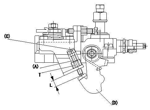
0000001801 STARTING I/Q ADJUSTMENT

Starting Q decrease lever adjustment
Adjust using the screw (A) so that the standards are satisfied, then fix using the nut (B).
Screw (B) protrusion: L
(C) = Cap
(D) = Stop lever
----------
L=7.4~11.1mm
----------
L=7.4~11.1mm T=6~9Nm(0.6~0.9kgfm)
----------
L=7.4~11.1mm
----------
L=7.4~11.1mm T=6~9Nm(0.6~0.9kgfm)