
Rating:
Information injection-pump assembly
ZEXEL
104741-6630
1047416630
ISUZU
8943820510
8943820510
Cross reference number
ZEXEL
104741-6630
1047416630
ISUZU
8943820510
8943820510
Zexel num
Bosch num
Firm num
Name
Calibration Data:
Adjustment conditions
Test oil
1404 Test oil ISO4113orSAEJ967d
1404 Test oil ISO4113orSAEJ967d
Test oil temperature
degC
45
45
50
Nozzle
105000-2010
Bosch type code
NP-DN12SD12TT
Nozzle holder
105780-2080
Opening pressure
MPa
14.7
14.7
15.19
Opening pressure
kgf/cm2
150
150
155
Injection pipe
Inside diameter - outside diameter - length (mm) mm 2-6-840
Inside diameter - outside diameter - length (mm) mm 2-6-840
Transfer pump pressure
kPa
20
20
20
Transfer pump pressure
kgf/cm2
0.2
0.2
0.2
Direction of rotation (viewed from drive side)
Right R
Right R
(Solenoid timer adjustment condition)
OFF
Injection timing adjustment
Pump speed
r/min
1150
1150
1150
Average injection quantity
mm3/st.
44.3
43.8
44.8
Difference in delivery
mm3/st.
3.5
Basic
*
Injection timing adjustment_02
Pump speed
r/min
2400
2400
2400
Average injection quantity
mm3/st.
16.1
12.6
19.6
Injection timing adjustment_03
Pump speed
r/min
1150
1150
1150
Average injection quantity
mm3/st.
44.3
43.3
45.3
Injection timing adjustment_04
Pump speed
r/min
700
700
700
Average injection quantity
mm3/st.
34.4
31.9
36.9
Injection timing adjustment_05
Pump speed
r/min
500
500
500
Average injection quantity
mm3/st.
29.5
26
33
Injection quantity adjustment
Pump speed
r/min
2400
2400
2400
Average injection quantity
mm3/st.
16.1
13.1
19.1
Difference in delivery
mm3/st.
4.5
Basic
*
Injection quantity adjustment_02
Pump speed
r/min
2500
2500
2500
Average injection quantity
mm3/st.
12
Governor adjustment
Pump speed
r/min
385
385
385
Average injection quantity
mm3/st.
6
4
8
Difference in delivery
mm3/st.
2
Basic
*
Governor adjustment_02
Pump speed
r/min
500
500
500
Average injection quantity
mm3/st.
3
Governor adjustment_03
Pump speed
r/min
385
385
385
Average injection quantity
mm3/st.
6
4
8
Timer adjustment
Pump speed
r/min
100
100
100
Average injection quantity
mm3/st.
80
60
100
Basic
*
Speed control lever angle
Pump speed
r/min
385
385
385
Average injection quantity
mm3/st.
0
0
0
Remarks
Magnet OFF
Magnet OFF
0000000901
Pump speed
r/min
1600
1600
1600
Overflow quantity with S/T ON
cm3/min
501
372
630
Overflow quantity with S/T OFF
cm3/min
531
402
660
Stop lever angle
Pump speed
r/min
1600
1600
1600
Pressure
kPa
490.5
471
510
Pressure
kgf/cm2
5
4.8
5.2
Basic
*
Stop lever angle_02
Pump speed
r/min
1600
1600
1600
Pressure with S/T OFF
kPa
490.5
471
510
Pressure with S/T OFF
kgf/cm2
5
4.8
5.2
Stop lever angle_03
Pump speed
r/min
2000
2000
2000
Pressure with S/T OFF
kPa
608
579
637
Pressure with S/T OFF
kgf/cm2
6.2
5.9
6.5
0000001101
Pump speed
r/min
1600
1600
1600
Timer stroke
mm
5.5
5.3
5.7
Basic
*
_02
Pump speed
r/min
670
670
670
Timer stroke with S/T ON
mm
0.5
0.5
_03
Pump speed
r/min
1000
1000
1000
Timer stroke with S/T OFF
mm
1
0.6
1.4
_04
Pump speed
r/min
1600
1600
1600
Timer stroke with S/T OFF
mm
5.5
5.2
5.8
_05
Pump speed
r/min
2000
2000
2000
Timer stroke with S/T OFF
mm
7.8
7.4
8.2
0000001201
Max. applied voltage
V
8
8
8
Test voltage
V
13
12
14
Timing setting
K dimension
mm
2.8
2.7
2.9
KF dimension
mm
5
4.9
5.1
MS dimension
mm
1
0.9
1.1
Pre-stroke
mm
0.45
0.43
0.47
Control lever angle alpha
deg.
18
14
22
Control lever angle beta
deg.
37
32
42
Test data Ex:
0000001801 V-FICD ADJUSTMENT
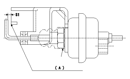
Adjustment of the V-FICD
1. Adjust the actuator rod to obtain S1.
2. Apply negative pressure P1 kPa {P2 mmHg} to the actuator and confirm that it moves through its full stroke.
(A) Control lever (Idling position)
----------
S1=1+1mm P1=-53.3kPa P2=-400mmHg
----------
S1=1+1mm
----------
S1=1+1mm P1=-53.3kPa P2=-400mmHg
----------
S1=1+1mm
0000001901 MICROSWITCH ADJUSTMENT
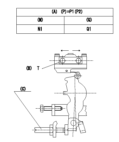
1. Fix dummy bolt (C) at N1 and Q1.
2. Move the microswitch in the direction of the arrow and fix it where it turns OFF.
3. Remove the dummy bolt (C) after the completion of adjustment. Confirm that the microswitch turns ON at the idle lever position and OFF at the full lever position.
(A): injection quantity standard
(P): Boost pressure
(N): Speed of the pump
(Q): Injection quantity
(B): Microswitch fixing bolt
----------
P1=-kPa P2=-mmHg N1=1000r/min Q1=7.5+-1cm3/1,000st
----------
P1=-kPa P2=-mmHg N1=1000r/min Q1=7.5+-1cm3/1,000st T=2~3N-m{0.2~0.3kgf-m}
----------
P1=-kPa P2=-mmHg N1=1000r/min Q1=7.5+-1cm3/1,000st
----------
P1=-kPa P2=-mmHg N1=1000r/min Q1=7.5+-1cm3/1,000st T=2~3N-m{0.2~0.3kgf-m}