Rating:
Information injection-pump assembly
ZEXEL
104741-3311
1047413311
MITSUBISHI
ME201433
me201433
Cross reference number
ZEXEL
104741-3311
1047413311
MITSUBISHI
ME201433
me201433
Zexel num
Bosch num
Firm num
Name
Calibration Data:
Adjustment conditions
Test oil
1404 Test oil ISO4113orSAEJ967d
1404 Test oil ISO4113orSAEJ967d
Test oil temperature
degC
45
45
50
Nozzle
105780-0060
Bosch type code
NP-DN0SD1510
Nozzle holder
105780-2150
Opening pressure
MPa
13
13
13.3
Opening pressure
kgf/cm2
133
133
136
Injection pipe
157805-7320
Injection pipe
Inside diameter - outside diameter - length (mm) mm 2-6-450
Inside diameter - outside diameter - length (mm) mm 2-6-450
Joint assembly
157641-4720
Tube assembly
157641-4020
Transfer pump pressure
kPa
20
20
20
Transfer pump pressure
kgf/cm2
0.2
0.2
0.2
Direction of rotation (viewed from drive side)
Right R
Right R
(Solenoid timer adjustment condition)
With S/T O-ring; S/T OFF. OFF
With S/T O-ring; S/T OFF. OFF
Injection timing adjustment
Pump speed
r/min
600
600
600
Boost pressure
kPa
31.3
30
32.6
Boost pressure
mmHg
235
225
245
Average injection quantity
mm3/st.
67.3
66.8
67.8
Difference in delivery
mm3/st.
5.5
Basic
*
Oil temperature
degC
50
48
52
Remarks
CBS
CBS
Injection timing adjustment_02
Pump speed
r/min
750
750
750
Boost pressure
kPa
0
0
0
Boost pressure
mmHg
0
0
0
Average injection quantity
mm3/st.
57.2
56.7
57.7
Difference in delivery
mm3/st.
4.5
Basic
*
Oil temperature
degC
50
48
52
Remarks
NA
NA
Injection timing adjustment_03
Pump speed
r/min
1000
1000
1000
Boost pressure
kPa
73.3
72
74.6
Boost pressure
mmHg
550
540
560
Average injection quantity
mm3/st.
81.3
80.8
81.8
Difference in delivery
mm3/st.
6.5
Basic
*
Oil temperature
degC
50
48
52
Remarks
Full
Full
Injection timing adjustment_04
Pump speed
r/min
600
600
600
Boost pressure
kPa
31.3
30
32.6
Boost pressure
mmHg
235
225
245
Average injection quantity
mm3/st.
67.3
66.3
68.3
Basic
*
Oil temperature
degC
50
48
52
Remarks
CBS
CBS
Injection timing adjustment_05
Pump speed
r/min
750
750
750
Boost pressure
kPa
0
0
0
Boost pressure
mmHg
0
0
0
Average injection quantity
mm3/st.
57.2
56.2
58.2
Oil temperature
degC
50
48
52
Injection timing adjustment_06
Pump speed
r/min
1000
1000
1000
Boost pressure
kPa
73.3
72
74.6
Boost pressure
mmHg
550
540
560
Average injection quantity
mm3/st.
81.3
80.3
82.3
Difference in delivery
mm3/st.
7
Basic
*
Oil temperature
degC
50
48
52
Remarks
Full
Full
Injection timing adjustment_07
Pump speed
r/min
2000
2000
2000
Boost pressure
kPa
73.3
72
74.6
Boost pressure
mmHg
550
540
560
Average injection quantity
mm3/st.
75.8
72.3
79.3
Oil temperature
degC
50
48
52
Injection quantity adjustment
Pump speed
r/min
2300
2300
2300
Boost pressure
kPa
73.3
72
74.6
Boost pressure
mmHg
550
540
560
Average injection quantity
mm3/st.
56.8
53.8
59.8
Difference in delivery
mm3/st.
17
Basic
*
Oil temperature
degC
52
50
54
Injection quantity adjustment_02
Pump speed
r/min
3000
3000
3000
Boost pressure
kPa
73.3
72
74.6
Boost pressure
mmHg
550
540
560
Average injection quantity
mm3/st.
12
Oil temperature
degC
55
52
58
Injection quantity adjustment_03
Pump speed
r/min
2300
2300
2300
Boost pressure
kPa
73.3
72
74.6
Boost pressure
mmHg
550
540
560
Average injection quantity
mm3/st.
56.8
51.8
61.8
Difference in delivery
mm3/st.
17.5
Basic
*
Oil temperature
degC
52
50
54
Governor adjustment
Pump speed
r/min
400
400
400
Boost pressure
kPa
0
0
0
Boost pressure
mmHg
0
0
0
Average injection quantity
mm3/st.
12.4
10.4
14.4
Difference in delivery
mm3/st.
2
Basic
*
Oil temperature
degC
48
46
50
Governor adjustment_02
Pump speed
r/min
400
400
400
Boost pressure
kPa
0
0
0
Boost pressure
mmHg
0
0
0
Average injection quantity
mm3/st.
12.4
9.9
14.9
Difference in delivery
mm3/st.
2.5
Basic
*
Oil temperature
degC
48
46
50
Governor adjustment_03
Pump speed
r/min
750
750
750
Boost pressure
kPa
0
0
0
Boost pressure
mmHg
0
0
0
Average injection quantity
mm3/st.
5
Oil temperature
degC
50
48
52
Timer adjustment
Pump speed
r/min
100
100
100
Boost pressure
kPa
0
0
0
Boost pressure
mmHg
0
0
0
Average injection quantity
mm3/st.
112
97
127
Basic
*
Oil temperature
degC
48
46
50
Remarks
IDLE
IDLE
Timer adjustment_02
Pump speed
r/min
100
100
100
Boost pressure
kPa
0
0
0
Boost pressure
mmHg
0
0
0
Average injection quantity
mm3/st.
110
90
130
Oil temperature
degC
48
46
50
Remarks
IDLE
IDLE
Speed control lever angle
Pump speed
r/min
400
400
400
Boost pressure
kPa
0
0
0
Boost pressure
mmHg
0
0
0
Average injection quantity
mm3/st.
0
0
0
Oil temperature
degC
48
46
50
Remarks
Magnet OFF at idling position
Magnet OFF at idling position
0000000901
Pump speed
r/min
1250
1250
1250
Boost pressure
kPa
73.3
72
74.6
Boost pressure
mmHg
550
540
560
Overflow quantity with S/T ON
cm3/min
740
610
870
Oil temperature
degC
50
48
52
Stop lever angle
Pump speed
r/min
1250
1250
1250
Boost pressure
kPa
73.3
72
74.6
Boost pressure
mmHg
550
540
560
Pressure with S/T ON
kPa
559
520
598
Pressure with S/T ON
kgf/cm2
5.7
5.3
6.1
Pressure with S/T OFF
kPa
510
490
530
Pressure with S/T OFF
kgf/cm2
5.2
5
5.4
Basic
*
Oil temperature
degC
50
48
52
Remarks
OFF
OFF
Stop lever angle_02
Pump speed
r/min
700
700
700
Boost pressure
kPa
73.3
72
74.6
Boost pressure
mmHg
550
540
560
Pressure with S/T OFF
kPa
373
324
422
Pressure with S/T OFF
kgf/cm2
3.8
3.3
4.3
Oil temperature
degC
50
48
52
Stop lever angle_03
Pump speed
r/min
1250
1250
1250
Boost pressure
kPa
73.3
72
74.6
Boost pressure
mmHg
550
540
560
Pressure with S/T ON
kPa
559
510
608
Pressure with S/T ON
kgf/cm2
5.7
5.2
6.2
Pressure with S/T OFF
kPa
510
481
539
Pressure with S/T OFF
kgf/cm2
5.2
4.9
5.5
Basic
*
Oil temperature
degC
50
48
52
Remarks
OFF
OFF
Stop lever angle_04
Pump speed
r/min
2000
2000
2000
Boost pressure
kPa
73.3
72
74.6
Boost pressure
mmHg
550
540
560
Pressure with S/T OFF
kPa
667
618
716
Pressure with S/T OFF
kgf/cm2
6.8
6.3
7.3
Oil temperature
degC
50
48
52
0000001101
Pump speed
r/min
1250
1250
1250
Boost pressure
kPa
73.3
72
74.6
Boost pressure
mmHg
550
540
560
Timer stroke with S/T ON
mm
6.6
6.1
7.1
Timer stroke with S/T OFF
mm
5.5
5.3
5.7
Basic
*
Oil temperature
degC
50
48
52
Remarks
OFF
OFF
_02
Pump speed
r/min
700
700
700
Boost pressure
kPa
73.3
72
74.6
Boost pressure
mmHg
550
540
560
Timer stroke with S/T ON
mm
3.3
2.6
4
Timer stroke with S/T OFF
mm
1.9
1.4
2.4
Oil temperature
degC
50
48
52
_03
Pump speed
r/min
1250
1250
1250
Boost pressure
kPa
73.3
72
74.6
Boost pressure
mmHg
550
540
560
Timer stroke with S/T ON
mm
6.6
5.9
7.3
Timer stroke with S/T OFF
mm
5.5
5.1
5.9
Basic
*
Oil temperature
degC
50
48
52
_04
Pump speed
r/min
1500
1500
1500
Boost pressure
kPa
73.3
72
74.6
Boost pressure
mmHg
550
540
560
Timer stroke with S/T OFF
mm
6.8
6.2
7.4
Oil temperature
degC
50
48
52
_05
Pump speed
r/min
2000
2000
2000
Boost pressure
kPa
73.3
72
74.6
Boost pressure
mmHg
550
540
560
Timer stroke with S/T OFF
mm
9.4
8.6
10.2
Oil temperature
degC
50
48
52
_06
Pump speed
r/min
2300
2300
2300
Boost pressure
kPa
73.3
72
74.6
Boost pressure
mmHg
550
540
560
Timer stroke with S/T OFF
mm
9.8
9.3
10.2
Oil temperature
degC
52
50
54
0000001201
Max. applied voltage
V
8
8
8
Test voltage
V
13
12
14
Timing setting
K dimension
mm
3.3
3.2
3.4
KF dimension
mm
6.01
5.91
6.11
MS dimension
mm
0.7
0.6
0.8
BCS stroke
mm
5.5
5.3
5.7
Control lever angle alpha
deg.
59
55
63
Control lever angle beta
deg.
39
34
44
Test data Ex:
0000001601 BOOST COMPENSATOR ADJUSTMENT
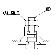
BCS adjustment procedure
1. At full boost pressure, set so that the full injection quantity is within the specifications (adjusting point).
2. Perform boost compensator intermediate operation point adjustment (pump speed N1, boost pressure P1).
3. When injection quantity at boost pressure P2 and pump speed N2 is not as specified, loosen nut (A) and adjust position of screw (B) so that injection quantity is as specified. The screw position should be within +-1 turn of initial position.
4. The nut tightening torque is T.
----------
N1=600r/min N2=750r/min P1=31.3kPa(235mmHg) P2=0kPa(0mmHg) T=6~9N-m(0.6~0.9kgf-m)
----------
SW=10mm T=6~9N-m(0.6~0.9kgf-m)
----------
N1=600r/min N2=750r/min P1=31.3kPa(235mmHg) P2=0kPa(0mmHg) T=6~9N-m(0.6~0.9kgf-m)
----------
SW=10mm T=6~9N-m(0.6~0.9kgf-m)
0000001801 POTENTIOMETER ADJUSTMENT
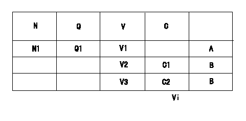
Adjustment of the potentiometer
Dummy bolt method
1. Hold the dummy bolt against the control lever at position N = N1 and Q = Q1 and fix using the lock nut.
2. At potentiometer adjustment, with the control lever contacting the dummy bolt, adjust the potentiometer so that the output voltage is V1.
3. After adjustment, remove the dummy bolt and confirm that the potentiometer output voltage at the control lever's idling and full speed positions is as specified above.
N:Pump speed
Q:Injection quantity
V:Output voltage
A:Adjusting point
B:Checking point
C:Position of the control lever
C1:Idling
C2:Full speed
Vi:Applied voltage
----------
N1=750r/min Q1=36.4+-1mm3/st V1=5.35+-0.03V
----------
N1=750r/min V1=5.35+-0.03V V2=1.94+-0.52V V3=8.58+-0.76V Q1=36.4+-1.0mm3/st Vi=10V
----------
N1=750r/min Q1=36.4+-1mm3/st V1=5.35+-0.03V
----------
N1=750r/min V1=5.35+-0.03V V2=1.94+-0.52V V3=8.58+-0.76V Q1=36.4+-1.0mm3/st Vi=10V
0000001901 W-CSD ADJUSTMENT
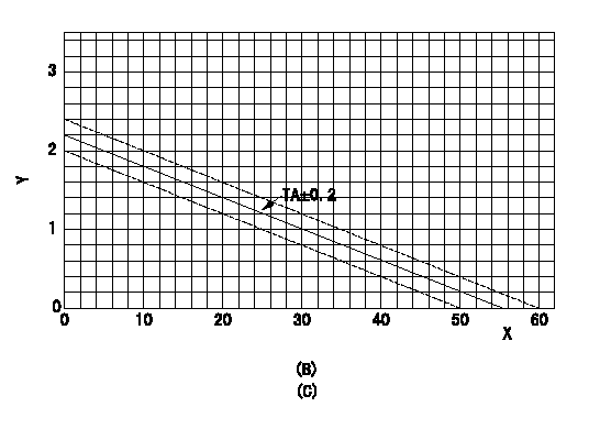
Adjustment of the W-CSD
Adjustment of the timer advance angle
Determine the timers stroke value from the graph and then adjust using the adjusting bolt.
(B) Timer stroke graph
(C) Graph TA = -0.04t+2.2 (0<= t deg C)
X:Temperature t (deg C)
Y:Timer stroke TA (mm)
----------
----------
----------
----------
0000002001 W-FICD LEVER ADJUSTMENT
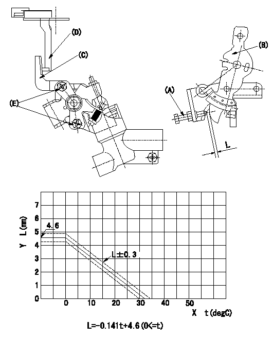
W-FICD adjustment
(1)Insert a block gauge L1 determined from the graph between the control lever (B) and the idling set screw (A).
(2)Fix bolt (E) in the position where W-FICD lever (C) contacts the control lever (D). (Tighten to torque T.)
(3)Remove the block gauge and shims after completing adjustment.
Caution: The temperature of the wax at adjustment must not exceed a.
Y = control lever dimension L (control lever position)
X = temperature t (deg C)
----------
L1=L+-0.3mm T=3.4~4.9N-m(0.35~0.5kgf-m) a=35degC
----------
----------
L1=L+-0.3mm T=3.4~4.9N-m(0.35~0.5kgf-m) a=35degC
----------
0000002101 V-FICD ADJUSTMENT
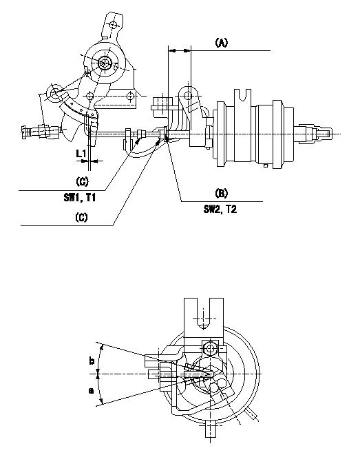
Adjustment of the two stage actuator (FICD).
(1)Attach the 2-stage actuator to the injection pump.
(2)Position the control lever in the idling position.
(3)Adjust using nut (C) so that the clearance between the control lever and the rod is L1.
(4)Actuator stroke adjustment is not necessary.
(5)Allowable angle when adjusting the rod position: c
(A): Actuator stroke
(B): Stroke adjusting nut
(C): Rod position adjusting nut
----------
L1=1+1mm c=+-20deg
----------
L1=1+1mm SW1=SW7 SW2=SW8 T1=1.4~2.0N-m(0.14~0.2kgf-m) T2=3.4~4.9N-m(0.35~0.5kgf-m) a=20deg b=20deg
----------
L1=1+1mm c=+-20deg
----------
L1=1+1mm SW1=SW7 SW2=SW8 T1=1.4~2.0N-m(0.14~0.2kgf-m) T2=3.4~4.9N-m(0.35~0.5kgf-m) a=20deg b=20deg