
Rating:
Information injection-pump assembly
BOSCH
9 460 612 914
9460612914
ZEXEL
104740-7710
1047407710
NISSAN-DIESEL
167001H601
167001h601
Components :
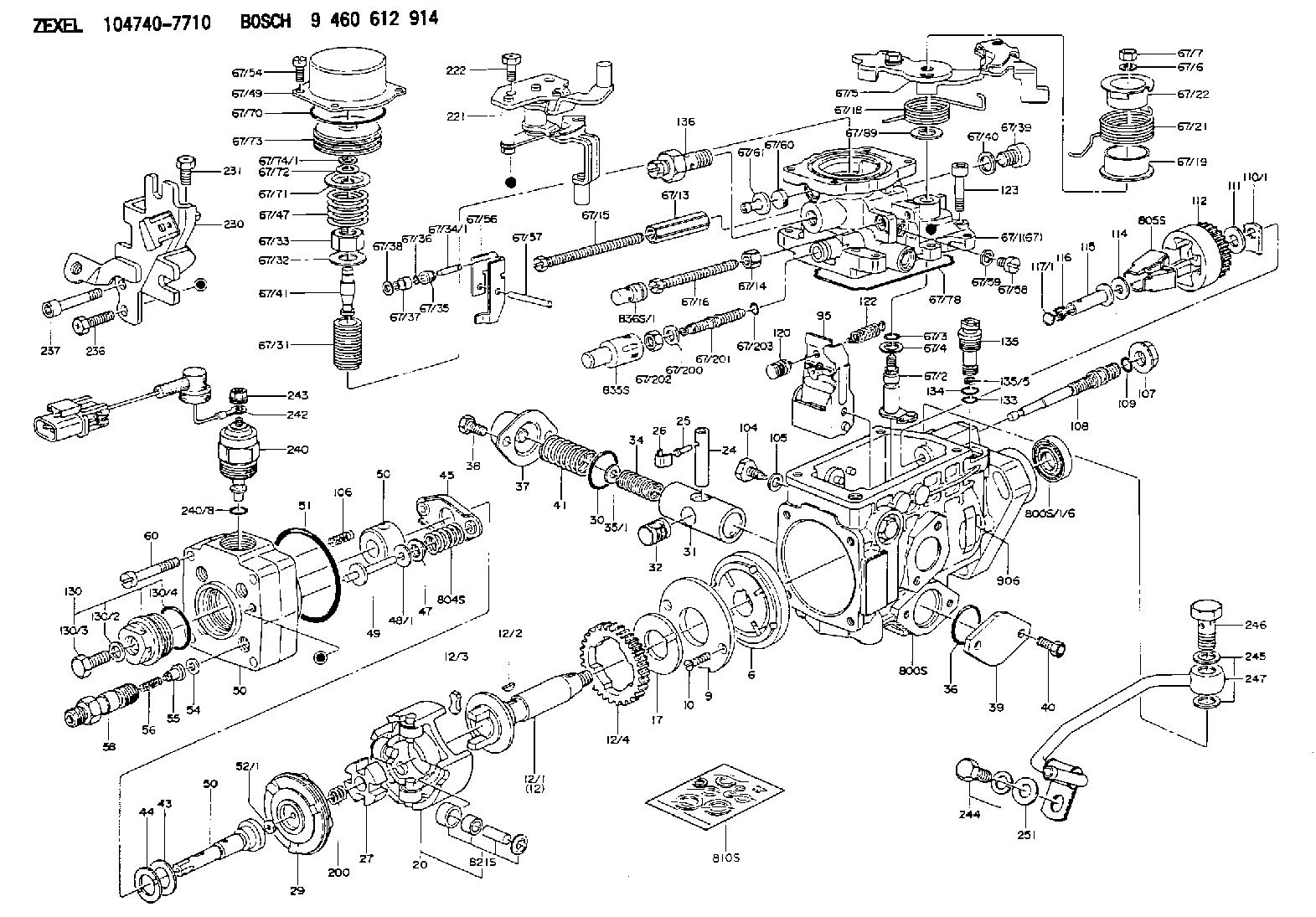
| 0. | INJECTION-PUMP ASSEMBLY | 104740-7710 |
| 1. | _ | |
| 2. | FUEL INJECTION PUMP | 104640-7710 |
| 3. | NUMBER PLATE | 146951-7000 |
| 4. | _ | |
| 5. | CAPSULE | |
| 6. | ADJUSTING DEVICE | |
| 7. | NOZZLE AND HOLDER ASSY | 105148-1121 |
| 8. | Nozzle and Holder | 16600-43G03 |
| 9. | Open Pre:MPa(Kqf/cm2) | 9.8{100} |
| 10. | NOZZLE-HOLDER | 105078-0050 |
| 11. | NOZZLE | 105007-1130 |
Scheme ###:
| 1/6. | [1] | 146601-0900 | PACKING RING |
| 6. | [1] | 146100-0420 | SUPPLY PUMP |
| 9. | [1] | 146103-0100 | COVER |
| 10. | [2] | 139104-0000 | FLAT-HEAD SCREW |
| 12. | [1] | 146200-0020 | DRIVE SHAFT |
| 12/1. | [1] | 146200-0000 | DRIVE SHAFT |
| 12/2. | [1] | 146201-0000 | WOODRUFF KEY |
| 12/3. | [2] | 146202-0100 | DAMPER |
| 12/4. | [1] | 146203-0000 | TOOTHED GEAR |
| 17. | [1] | 146204-0000 | PLAIN WASHER |
| 20. | [1] | 146210-2320 | ROLLER SET |
| 24. | [1] | 146303-0000 | BEARING PIN |
| 25. | [1] | 146304-0000 | BEARING PIN |
| 26. | [1] | 146305-0000 | CLAMPING BAND |
| 27. | [1] | 146205-0000 | SLOTTED WASHER |
| 29. | [1] | 146220-2120 | CAM PLATE |
| 30. | [1] | 146600-0800 | O-RING |
| 31. | [1] | 146311-6020 | PUMP PLUNGER |
| 32. | [1] | 146301-0000 | SLIDING PIECE |
| 34. | [1] | 146312-3000 | COMPRESSION SPRING |
| 34B. | [1] | 146312-2900 | COMPRESSION SPRING |
| 34C. | [1] | 146312-1800 | COMPRESSION SPRING |
| 35/1. | [1] | 146690-3200 | SHIM D11.5&9.4T0.1 |
| 35/1. | [1] | 146690-3300 | SHIM D11.5&9.4T0.2 |
| 35/1. | [1] | 146690-3400 | SHIM D11.5&9.4T0.25 |
| 35/1. | [1] | 146690-3500 | SHIM D11.5&9.4T1.0 |
| 35/1. | [1] | 146690-4100 | SHIM D11.5&9.4T2 |
| 35/1. | [1] | 146690-4200 | SHIM D11.5&9.4T0.5 |
| 35/1. | [1] | 146690-4300 | SHIM D11.5&9.4T0.75 |
| 36. | [1] | 146600-0800 | O-RING |
| 37. | [1] | 146310-4020 | COVER |
| 38. | [2] | 146620-5000 | BLEEDER SCREW |
| 39. | [1] | 146310-0100 | COVER |
| 40. | [2] | 146620-5000 | BLEEDER SCREW |
| 41. | [1] | 146312-1900 | COMPRESSION SPRING |
| 43. | [1] | 146230-0000 | SHIM |
| 44. | [1] | 146230-0100 | PLAIN WASHER |
| 45. | [1] | 146231-0001 | SLOTTED WASHER |
| 47. | [2] | 146233-0000 | SLOTTED WASHER |
| 48/1. | [1] | 146603-0100 | SHIM D17.0&5.2T0.80 |
| 48/1. | [1] | 146603-0200 | SHIM D17.0&5.2T1.00 |
| 48/1. | [1] | 146603-0300 | SHIM D17.0&5.2T1.20 |
| 48/1. | [1] | 146603-0400 | SHIM D17.0&5.2T1.50 |
| 48/1. | [1] | 146690-1400 | SHIM D17&5.2T0.9 |
| 48/1. | [1] | 146690-1500 | SHIM D17&5.2T1.1 |
| 48/1. | [1] | 146690-1600 | SHIM D17&5.2T1.3 |
| 48/1. | [1] | 146690-1700 | SHIM D17&5.2T1.4 |
| 48/1. | [1] | 146690-1800 | SHIM D17&5.2T1.6 |
| 49. | [2] | 146234-0500 | GUIDE PIN |
| 50. | [1] | 146401-0520 | HYDRAULIC HEAD |
| 50. | [1] | 146401-0520 | HYDRAULIC HEAD |
| 50. | [1] | 146401-0520 | HYDRAULIC HEAD |
| 51. | [1] | 146600-0000 | O-RING |
| 52/1. | [1] | 146420-0200 | SHIM D9.5&3.0T1.94 |
| 52/1. | [1] | 146420-0700 | SHIM D9.5&3.0T2.04 |
| 52/1. | [1] | 146420-1200 | SHIM D9.5&3.0T2.14 |
| 52/1. | [1] | 146420-1700 | SHIM D9.5&3.0T2.24 |
| 52/1. | [1] | 146420-2200 | SHIM D9.5&3.0T2.34 |
| 52/1. | [1] | 146420-2700 | SHIM D9.5&3.0T2.44 |
| 52/1. | [1] | 146420-3200 | SHIM D9.5&3.0T2.54 |
| 52/1. | [1] | 146420-3700 | SHIM D9.5&3.0T2.64 |
| 52/1. | [1] | 146420-5600 | SHIM D9.5&3.0T1.84 |
| 54. | [4] | 146433-0100 | GASKET |
| 55. | [4] | 146430-0320 | DELIVERY-VALVE ASSEMBLY VE4 |
| 56. | [4] | 146432-0000 | COMPRESSION SPRING |
| 58. | [4] | 146440-0220 | FITTING |
| 60. | [3] | 139106-0100 | FLAT-HEAD SCREW |
| 67. | [1] | 146706-2320 | ANEROID CAPSULE |
| 67/1. | [1] | 146508-9921 | GOVERNOR COVER |
| 67/2. | [1] | 146515-2820 | CONTROL SHAFT |
| 67/3. | [1] | 146600-0100 | O-RING |
| 67/4. | [1] | 139310-0200 | PLAIN WASHER |
| 67/5. | [1] | 146537-7020 | CONTROL LEVER |
| 67/6. | [1] | 014110-6440 | LOCKING WASHER D12.2&6.1T1.5 |
| 67/7. | [1] | 013020-6040 | UNION NUT |
| 67/13. | [1] | 139206-0100 | UNION NUT |
| 67/14. | [1] | 146621-1700 | UNION NUT |
| 67/15. | [1] | 146526-4200 | BLEEDER SCREW |
| 67/16. | [1] | 146526-3000 | BLEEDER SCREW |
| 67/18. | [1] | 146587-6900 | COILED SPRING |
| 67/19. | [1] | 146541-3000 | BUSHING |
| 67/21. | [1] | 146587-6800 | COILED SPRING |
| 67/22. | [1] | 146541-3100 | SLOTTED WASHER |
| 67/31. | [1] | 146710-0400 | BUSHING |
| 67/32. | [1] | 146602-1800 | PLAIN WASHER |
| 67/33. | [1] | 146716-0200 | UNION NUT |
| 67/34/1. | [1] | 146713-1000 | BEARING PIN L24.6 |
| 67/34/1. | [1] | 146713-1100 | BEARING PIN L24.8 |
| 67/34/1. | [1] | 146713-1200 | BEARING PIN L25.0 |
| 67/34/1. | [1] | 146713-1300 | BEARING PIN L25.2 |
| 67/34/1. | [1] | 146713-1400 | BEARING PIN L25.4 |
| 67/35. | [1] | 146621-0300 | UNION NUT |
| 67/36. | [1] | 146600-1400 | O-RING |
| 67/37. | [1] | 146710-0100 | BUSHING |
| 67/38. | [1] | 139506-0200 | GASKET |
| 67/39. | [1] | 146620-0300 | CAPSULE |
| 67/40. | [1] | 026512-1540 | GASKET |
| 67/41. | [1] | 146713-2400 | ADJUSTING PIN |
| 67/47. | [1] | 146717-0200 | COILED SPRING |
| 67/49. | [1] | 146721-0700 | COVER |
| 67/54. | [4] | 139006-4400 | BLEEDER SCREW |
| 67/56. | [1] | 146723-0300 | CONTROL LEVER |
| 67/57. | [1] | 146712-0100 | BEARING PIN |
| 67/58. | [2] | 146620-0600 | CAPSULE |
| 67/59. | [2] | 026506-1040 | GASKET |
| 67/60. | [1] | 146724-0300 | ELEMENT |
| 67/61. | [1] | 146724-0400 | CAPSULE |
| 67/70. | [1] | 016520-6010 | O-RING |
| 67/71. | [1] | 146714-0100 | SLOTTED WASHER |
| 67/72. | [1] | 016010-0920 | LOCKING WASHER |
| 67/73. | [1] | 146715-0120 | BELLOWS |
| 67/74/1. | [0] | 146603-3700 | SHIM T0.20 |
| 67/74/1. | [0] | 146603-3800 | SHIM T0.30 |
| 67/74/1. | [0] | 146603-3900 | SHIM T0.50 |
| 67/74/1. | [0] | 146603-4000 | SHIM T0.70 |
| 67/74/1. | [0] | 146603-4100 | SHIM T1.00 |
| 67/74/1. | [0] | 146603-4200 | SHIM T1.50 |
| 67/78. | [1] | 146600-4400 | SEAL RING |
| 67/89. | [1] | 146541-4900 | PLAIN WASHER |
| 67/200. | [1] | 139308-0300 | PLAIN WASHER |
| 67/201. | [1] | 146545-3400 | THREADED PIN L53.00 |
| 67/201B. | [1] | 146545-3500 | THREADED PIN L55.00 |
| 67/201C. | [1] | 146545-3600 | THREADED PIN L57.00 |
| 67/202. | [1] | 139208-0900 | UNION NUT |
| 67/203. | [1] | 146600-1200 | O-RING |
| 95. | [1] | 146551-6920 | FULCRUM LEVER |
| 104. | [2] | 146568-0000 | SLOTTED SPRING PIN |
| 105. | [2] | 026508-1140 | GASKET D11.4&8.2T1.0 |
| 106. | [2] | 146588-0500 | COILED SPRING |
| 107. | [1] | 146569-0300 | UNION NUT |
| 108. | [1] | 146570-0100 | GOVERNOR SHAFT |
| 109. | [1] | 146600-0400 | O-RING |
| 110/1. | [1] | 146571-0000 | SHIM D20.2&8.3T1.05 |
| 110/1. | [1] | 146571-0100 | SHIM D20.2&8.3T1.25 |
| 110/1. | [1] | 146571-0200 | SHIM D20.2&8.3T1.45 |
| 110/1. | [1] | 146571-0300 | SHIM D20.2&8.3T1.65 |
| 110/1. | [1] | 146571-0400 | SHIM D20.2&8.3T1.85 |
| 111. | [1] | 146602-0600 | PLAIN WASHER |
| 112. | [1] | 146572-0020 | FLYWEIGHT ASSEMBLY |
| 114. | [1] | 146602-0500 | PLAIN WASHER |
| 115. | [1] | 146975-2500 | SLIDING SLEEVE |
| 116. | [1] | 146576-0000 | SEALING CAP |
| 117/1. | [1] | 146577-0800 | PLUG L3.30 |
| 117/1. | [1] | 146577-0900 | PLUG L3.50 |
| 117/1. | [1] | 146577-1000 | PLUG L3.70 |
| 117/1. | [1] | 146577-1100 | PLUG L3.90 |
| 117/1. | [1] | 146577-1200 | PLUG L4.10 |
| 117/1. | [1] | 146577-1300 | PLUG L4.30 |
| 117/1. | [1] | 146577-1400 | PLUG L4.50 |
| 117/1. | [1] | 146577-1500 | PLUG L4.70 |
| 117/1. | [1] | 146577-5700 | PLUG L3.2 |
| 117/1. | [1] | 146577-5800 | PLUG L3.4 |
| 117/1. | [1] | 146577-5900 | PLUG L3.6 |
| 117/1. | [1] | 146577-6000 | PLUG L3.8 |
| 117/1. | [1] | 146577-6100 | PLUG L4.0 |
| 117/1. | [1] | 146577-6200 | PLUG L4.2 |
| 117/1. | [1] | 146577-6300 | PLUG L4.4 |
| 117/1. | [1] | 146577-6400 | PLUG L4.6 |
| 117/1. | [1] | 146577-6500 | PLUG L4.8 |
| 120. | [1] | 146579-6020 | RETAINING PIN |
| 122. | [1] | 146580-0400 | GOVERNOR SPRING |
| 123. | [4] | 146620-0500 | HEX-SOCKET-HEAD CAP SCREW |
| 130. | [1] | 146421-0020 | CAPSULE |
| 130/2. | [1] | 026508-1140 | GASKET D11.4&8.2T1.0 |
| 130/3. | [1] | 146422-0000 | BLEEDER SCREW |
| 130/4. | [1] | 146600-0500 | O-RING |
| 133. | [1] | 146600-0600 | O-RING |
| 134. | [1] | 146600-0700 | O-RING |
| 135. | [1] | 146110-0220 | CONTROL VALVE STAMP 02 |
| 135/5. | [1] | 146114-0000 | SPRING WASHER |
| 136. | [1] | 146120-0120 | OVER FLOW VALVE |
| 200. | [1] | 146206-0100 | COILED SPRING |
| 221. | [1] | 146925-6920 | BRACKET |
| 222. | [2] | 139006-4600 | BLEEDER SCREW |
| 230. | [1] | 146925-9120 | BRACKET |
| 231. | [1] | 139006-4600 | BLEEDER SCREW |
| 236. | [1] | 139006-4800 | BLEEDER SCREW |
| 237. | [1] | 146620-0200 | HEX-SOCKET-HEAD CAP SCREW |
| 240. | [1] | 146650-1220 | PULLING ELECTROMAGNET |
| 240/8. | [1] | 146600-1700 | O-RING |
| 242. | [1] | 146658-6120 | WIRE |
| 243. | [1] | 146621-1000 | UNION NUT |
| 244. | [1] | 020118-1440 | BLEEDER SCREW |
| 245. | [2] | 139512-0500 | GASKET |
| 246. | [1] | 027412-2440 | EYE BOLT |
| 247. | [1] | 146607-8520 | PIPE |
| 251. | [1] | 014010-8140 | PLAIN WASHER |
| 800S. | [1] | 146019-4420 | PUMP HOUSING |
| 800S/1/6. | [1] | 146601-0900 | PACKING RING |
| 804S. | [1] | 146232-0320 | COMPRESSION SPRING |
| 805S. | [1] | 146574-0120 | PARTS SET |
| 810S. | [1] | 146600-1120 | REPAIR SET |
| 821S. | [1] | 146210-5720 | ROLLER SET |
| 835S. | [1] | 146598-1000 | CAP |
| 836S/1. | [1] | 146598-0600 | CAP L18 |
| 836S/1. | [1] | 146598-0700 | CAP L21 |
| 836S/1. | [1] | 146598-0800 | CAP L24 |
| 836S/1. | [1] | 146598-0900 | CAP L27 |
| 906. | [1] | 146951-7000 | NAMEPLATE |
Include in #2:
104740-7710
as INJECTION-PUMP ASSEMBLY
Cross reference number
BOSCH
9 460 612 914
9460612914
ZEXEL
104740-7710
1047407710
NISSAN-DIESEL
167001H601
167001h601
Zexel num
Bosch num
Firm num
Name
104740-7710
9 460 612 914
167001H601 NISSAN-DIESEL
INJECTION-PUMP ASSEMBLY
TD25 * K
TD25 * K
Calibration Data:
Adjustment conditions
Test oil
1404 Test oil ISO4113orSAEJ967d
1404 Test oil ISO4113orSAEJ967d
Test oil temperature
degC
45
45
50
Nozzle
105000-2010
Bosch type code
NP-DN12SD12TT
Nozzle holder
105780-2080
Opening pressure
MPa
14.7
14.7
15.19
Opening pressure
kgf/cm2
150
150
155
Injection pipe
Inside diameter - outside diameter - length (mm) mm 2-6-840
Inside diameter - outside diameter - length (mm) mm 2-6-840
Transfer pump pressure
kPa
20
20
20
Transfer pump pressure
kgf/cm2
0.2
0.2
0.2
Direction of rotation (viewed from drive side)
Right R
Right R
Injection timing adjustment
Pump speed
r/min
1100
1100
1100
Average injection quantity
mm3/st.
45.8
45.3
46.3
Difference in delivery
mm3/st.
3
Basic
*
Injection timing adjustment_02
Pump speed
r/min
2500
2500
2500
Average injection quantity
mm3/st.
12.1
9.6
14.6
Injection timing adjustment_03
Pump speed
r/min
2300
2300
2300
Average injection quantity
mm3/st.
32.8
28.3
37.3
Injection timing adjustment_04
Pump speed
r/min
2150
2150
2150
Average injection quantity
mm3/st.
37.9
35.8
40
Injection timing adjustment_05
Pump speed
r/min
1100
1100
1100
Average injection quantity
mm3/st.
45.8
44.8
46.8
Injection timing adjustment_06
Pump speed
r/min
600
600
600
Average injection quantity
mm3/st.
44.4
42.4
46.4
Injection quantity adjustment
Pump speed
r/min
2500
2500
2500
Average injection quantity
mm3/st.
12.1
10.1
14.1
Basic
*
Injection quantity adjustment_02
Pump speed
r/min
2700
2700
2700
Average injection quantity
mm3/st.
5
Governor adjustment
Pump speed
r/min
350
350
350
Average injection quantity
mm3/st.
6.5
4.5
8.5
Difference in delivery
mm3/st.
2
Basic
*
Governor adjustment_02
Pump speed
r/min
450
450
450
Average injection quantity
mm3/st.
3
Governor adjustment_03
Pump speed
r/min
350
350
350
Average injection quantity
mm3/st.
6.5
4.5
8.5
Timer adjustment
Pump speed
r/min
100
100
100
Average injection quantity
mm3/st.
62.5
45
80
Basic
*
Speed control lever angle
Pump speed
r/min
350
350
350
Average injection quantity
mm3/st.
0
0
0
Remarks
Magnet OFF
Magnet OFF
0000000901
Pump speed
r/min
1100
1100
1100
Overflow quantity with S/T ON
cm3/min
390
258
522
Stop lever angle
Pump speed
r/min
1100
1100
1100
Pressure
kPa
431.5
402
461
Pressure
kgf/cm2
4.4
4.1
4.7
Basic
*
Stop lever angle_02
Pump speed
r/min
1100
1100
1100
Pressure
kPa
431.5
402
461
Pressure
kgf/cm2
4.4
4.1
4.7
Stop lever angle_03
Pump speed
r/min
1700
1700
1700
Pressure
kPa
578.5
549
608
Pressure
kgf/cm2
5.9
5.6
6.2
Stop lever angle_04
Pump speed
r/min
2150
2150
2150
Pressure
kPa
676.5
647
706
Pressure
kgf/cm2
6.9
6.6
7.2
0000001101
Pump speed
r/min
1100
1100
1100
Timer stroke
mm
2.6
2.4
2.8
Basic
*
_02
Pump speed
r/min
1100
1100
1100
Timer stroke
mm
2.6
2.3
2.9
_03
Pump speed
r/min
1700
1700
1700
Timer stroke
mm
4.9
4.3
5.5
_04
Pump speed
r/min
2300
2300
2300
Timer stroke
mm
6.5
6
7
0000001201
Max. applied voltage
V
8
8
8
Test voltage
V
13
12
14
0000001501
Pump speed
r/min
1100
1100
1100
Atmospheric pressure difference
kPa
-21.9
-22.6
-21.2
Atmospheric pressure difference
mmHg
-164
-169
-159
Average injection quantity
mm3/st.
36.7
35.2
38.2
Basic
*
_02
Pump speed
r/min
1100
1100
1100
Atmospheric pressure difference
kPa
-21.9
-22.6
-21.2
Atmospheric pressure difference
mmHg
-164
-169
-159
Average injection quantity
mm3/st.
36.7
34.7
38.7
Timing setting
K dimension
mm
3.3
3.2
3.4
KF dimension
mm
5.8
5.7
5.9
MS dimension
mm
1
0.9
1.1
Control lever angle alpha
deg.
55.5
51.5
59.5
Control lever angle beta
deg.
36
31
41
Test data Ex:
0000001501 ANEROID COMPENSATOR
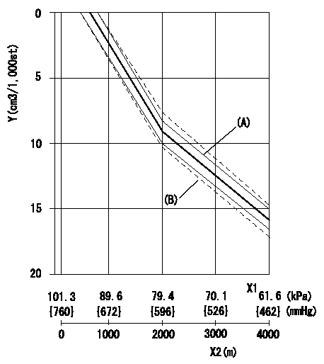
ACS adjustment
Full load injection quantity at high altitudes and ACS adjusting method
1. Full load injection quantity adjustment
(1)Remove the ACS cover and remove the bellows and adjusting shim.
(2)Perform all adjustments as per the adjustment standard except for ACS adjustment.
2. ACS adjustment
(1)Assemble the ACS cover, bellows and adjusting shim.
(2)At pump speed N1, adjust using a shim to obtain the decrease for the altitude shown in the table.
X1 = atmospheric pressure
X2 = altitude
Y = decrease quantity
(A) = adjustment value
(B) = test value
----------
N1=1100r/min
----------
----------
N1=1100r/min
----------
0000001801 CONTROL LEVER ANGLE
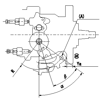
Control lever angle measurement
1. Measure dimension Ya between the end of the lever and the flange face B.
2. Measure the lever angle from the R (plate) pin hole.
(A) Lever angle measurement position
----------
Ya=8.4~12.2mm R=53mm
----------
Ya=8.4~12.2mm R=53mm Alpha=51.5~59.5deg Beta=31~41deg
----------
Ya=8.4~12.2mm R=53mm
----------
Ya=8.4~12.2mm R=53mm Alpha=51.5~59.5deg Beta=31~41deg
Have questions with 104740-7710?
Group cross 104740-7710 ZEXEL
Nissan-Diesel
Nissan
Nissan-Diesel
104740-7710
9 460 612 914
167001H601
INJECTION-PUMP ASSEMBLY
TD25
TD25