
Rating:
Information injection-pump assembly
ZEXEL
104740-4790
1047404790
Cross reference number
ZEXEL
104740-4790
1047404790
Zexel num
Bosch num
Firm num
Name
Calibration Data:
Adjustment conditions
Test oil
1404 Test oil ISO4113orSAEJ967d
1404 Test oil ISO4113orSAEJ967d
Test oil temperature
degC
45
45
50
Nozzle
105000-2010
Bosch type code
NP-DN12SD12TT
Nozzle holder
105780-2080
Opening pressure
MPa
14.7
14.7
15.19
Opening pressure
kgf/cm2
150
150
155
Injection pipe
Inside diameter - outside diameter - length (mm) mm 2-6-840
Inside diameter - outside diameter - length (mm) mm 2-6-840
Transfer pump pressure
kPa
20
20
20
Transfer pump pressure
kgf/cm2
0.2
0.2
0.2
Direction of rotation (viewed from drive side)
Right R
Right R
Injection timing adjustment
Pump speed
r/min
1000
1000
1000
Average injection quantity
mm3/st.
40.4
39.9
40.9
Difference in delivery
mm3/st.
3
Basic
*
Injection timing adjustment_02
Pump speed
r/min
2350
2350
2350
Average injection quantity
mm3/st.
14.7
11.2
18.2
Injection timing adjustment_03
Pump speed
r/min
2100
2100
2100
Average injection quantity
mm3/st.
35.7
33.6
37.8
Injection timing adjustment_04
Pump speed
r/min
1000
1000
1000
Average injection quantity
mm3/st.
40.4
39.4
41.4
Injection timing adjustment_05
Pump speed
r/min
600
600
600
Average injection quantity
mm3/st.
38.5
36.5
40.5
Injection quantity adjustment
Pump speed
r/min
2350
2350
2350
Average injection quantity
mm3/st.
14.7
11.7
17.7
Basic
*
Injection quantity adjustment_02
Pump speed
r/min
2450
2450
2450
Average injection quantity
mm3/st.
5
Governor adjustment
Pump speed
r/min
350
350
350
Average injection quantity
mm3/st.
6.5
4.5
8.5
Difference in delivery
mm3/st.
2
Basic
*
Governor adjustment_02
Pump speed
r/min
350
350
350
Average injection quantity
mm3/st.
6.5
4.5
8.5
Governor adjustment_03
Pump speed
r/min
400
400
400
Average injection quantity
mm3/st.
3
Timer adjustment
Pump speed
r/min
100
100
100
Average injection quantity
mm3/st.
62.5
45
80
Basic
*
Speed control lever angle
Pump speed
r/min
350
350
350
Average injection quantity
mm3/st.
0
0
0
Remarks
Magnet OFF
Magnet OFF
0000000901
Pump speed
r/min
1000
1000
1000
Overflow quantity
cm3/min
180
48
312
Stop lever angle
Pump speed
r/min
1000
1000
1000
Pressure
kPa
421.5
392
451
Pressure
kgf/cm2
4.3
4
4.6
Basic
*
Stop lever angle_02
Pump speed
r/min
600
600
600
Pressure
kPa
333.5
304
363
Pressure
kgf/cm2
3.4
3.1
3.7
Stop lever angle_03
Pump speed
r/min
1000
1000
1000
Pressure
kPa
421.5
392
451
Pressure
kgf/cm2
4.3
4
4.6
Stop lever angle_04
Pump speed
r/min
2100
2100
2100
Pressure
kPa
676.5
647
706
Pressure
kgf/cm2
6.9
6.6
7.2
0000001101
Pump speed
r/min
1000
1000
1000
Timer stroke
mm
1.7
1.5
1.9
Basic
*
_02
Pump speed
r/min
1000
1000
1000
Timer stroke
mm
1.7
1.4
2
_03
Pump speed
r/min
1400
1400
1400
Timer stroke
mm
3.3
2.7
3.9
_04
Pump speed
r/min
2100
2100
2100
Timer stroke
mm
6.2
5.6
6.8
0000001201
Max. applied voltage
V
8
8
8
Test voltage
V
13
12
14
Timing setting
K dimension
mm
3.3
3.2
3.4
KF dimension
mm
5.75
5.65
5.85
MS dimension
mm
1.2
1.1
1.3
Pre-stroke
mm
0.28
0.26
0.3
Control lever angle alpha
deg.
25
21
29
Control lever angle beta
deg.
42
37
47
Test data Ex:
0000001801 W-CSD ADJUSTMENT
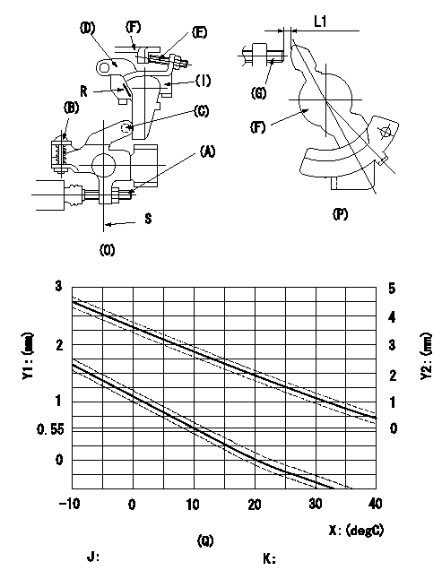
Adjustment of the W-CSD
1. Adjustment of the advance angle of the timer
(1)Determine the timer advance angle from the graph in Fig. 3 (Q).
(2)(1) Adjust with the screw (A) so that the timer advance angle determined in the item (1) is obtained.
2. Setting the intermediate lever position (refer to fig 1 and fig 2)
(1)Insert a block gauge L1 between the idling set screw (G) and the control lever (F).
(2)Align the intermediate lever (D) with the aligning line and position it perpendicularly. Adjust the screw (E) so that it contacts the control lever (F) and then tighten the nut.
3. W-CSD lever adjustment [refer to fig 1 (O) and fig 2 (P)]
(1)Insert a block gauge (I) L2 determined from the graph (L-theta) in figure 3 (Q) between the idling set screw (G) and the control lever (F).
(2)Fix screw (B) so that the W-CSD lever (C)'s roller contacts the intermediate lever (D). (Wax temperature at adjustment must not exceed a.)
Adjust the screw (B) until the screw (F) contacts the control lever (G). Then fix locknut (A).
Note:
When inserting the block gauge, separate lever (C) and (D) using screw (B) to prevent excessive force on the lever.
Q = aligning mark
S = intermediate lever perpendicular position
X:Temperature theta (X)
Y1:Timer stroke TA (mm)
Y2:Control lever L dimension (mm; control lever position)
J:Graph TA-X:
-10 <= X (deg C) <= 20: TA = -0.055X + 1.1
20 <= X (deg C) <= 40: TA = -0.0333X + 0.66
K:Graph L-X:
-10 <= X (deg C) <= 20: L = -0.0867X + 3.63
20 <= X (deg C) <= 40: L = -0.075 t + 3.4
----------
L1=1.9+-0.05mm L2=L1+-0.05mm a=30degC
----------
L1=1.9+-0.05mm
----------
L1=1.9+-0.05mm L2=L1+-0.05mm a=30degC
----------
L1=1.9+-0.05mm
0000001901 ACCELERATOR SWITCH ADJ
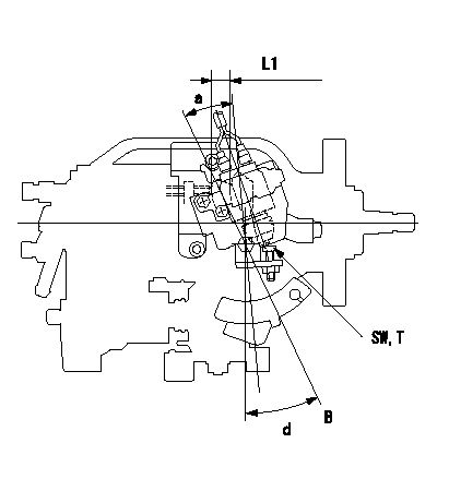
Accelerator switch adjustment
ON - OFF changeover point: from idle to a (shim thickness A = L)
Idle~c: ON
c~full: OFF
A = shim thickness
B = idle lever position
----------
a=20+-3deg b=20deg c=20deg L1=12.9mm
----------
a=20+-3deg d=25+-4deg SW=SW10 T=6~9N-m(0.6~0.9kgf-m) L1=12.9mm
----------
a=20+-3deg b=20deg c=20deg L1=12.9mm
----------
a=20+-3deg d=25+-4deg SW=SW10 T=6~9N-m(0.6~0.9kgf-m) L1=12.9mm