
Rating:
Information injection-pump assembly
ZEXEL
104740-2460
1047402460
Cross reference number
ZEXEL
104740-2460
1047402460
Zexel num
Bosch num
Firm num
Name
104740-2460
INJECTION-PUMP ASSEMBLY
Calibration Data:
Adjustment conditions
Test oil
1404 Test oil ISO4113orSAEJ967d
1404 Test oil ISO4113orSAEJ967d
Test oil temperature
degC
45
45
50
Nozzle
105000-2010
Bosch type code
NP-DN12SD12TT
Nozzle holder
105780-2080
Opening pressure
MPa
14.7
14.7
15.19
Opening pressure
kgf/cm2
150
150
155
Injection pipe
Inside diameter - outside diameter - length (mm) mm 2-6-840
Inside diameter - outside diameter - length (mm) mm 2-6-840
Transfer pump pressure
kPa
20
20
20
Transfer pump pressure
kgf/cm2
0.2
0.2
0.2
Direction of rotation (viewed from drive side)
Right R
Right R
Injection timing adjustment
Pump speed
r/min
600
600
600
Boost pressure
kPa
8
Boost pressure
mmHg
60
Average injection quantity
mm3/st.
30.2
29.7
30.7
Difference in delivery
mm3/st.
2
Basic
*
Remarks
Full
Full
Injection timing adjustment_02
Pump speed
r/min
900
900
900
Boost pressure
kPa
35.35
34
36.7
Boost pressure
mmHg
265
255
275
Average injection quantity
mm3/st.
40
39.5
40.5
Difference in delivery
mm3/st.
2
Basic
*
Remarks
CBS
CBS
Injection timing adjustment_03
Pump speed
r/min
2700
2700
2700
Boost pressure
kPa
64.55
63.2
65.9
Boost pressure
mmHg
484
474
494
Average injection quantity
mm3/st.
8.7
5.2
12.2
Injection timing adjustment_04
Pump speed
r/min
2200
2200
2200
Boost pressure
kPa
66.65
65.3
68
Boost pressure
mmHg
500
490
510
Average injection quantity
mm3/st.
36.8
34.8
38.8
Injection timing adjustment_05
Pump speed
r/min
900
900
900
Boost pressure
kPa
35.35
34
36.7
Boost pressure
mmHg
265
255
275
Average injection quantity
mm3/st.
40
39
41
Injection timing adjustment_06
Pump speed
r/min
600
600
600
Boost pressure
kPa
8
Boost pressure
mmHg
60
Average injection quantity
mm3/st.
30.2
29.2
31.2
Injection quantity adjustment
Pump speed
r/min
2700
2700
2700
Boost pressure
kPa
64.55
63.2
65.9
Boost pressure
mmHg
484
474
494
Average injection quantity
mm3/st.
9.7
6.7
12.7
Difference in delivery
mm3/st.
4.5
Basic
*
Injection quantity adjustment_02
Pump speed
r/min
2800
2800
2800
Boost pressure
kPa
64.55
63.2
65.9
Boost pressure
mmHg
484
474
494
Average injection quantity
mm3/st.
6
Governor adjustment
Pump speed
r/min
400
400
400
Boost pressure
kPa
8
Boost pressure
mmHg
60
Average injection quantity
mm3/st.
6.5
5.5
7.5
Difference in delivery
mm3/st.
2
Basic
*
Governor adjustment_02
Pump speed
r/min
400
400
400
Boost pressure
kPa
8
Boost pressure
mmHg
60
Average injection quantity
mm3/st.
6.5
5.5
7.5
Governor adjustment_03
Pump speed
r/min
500
500
500
Boost pressure
kPa
8
Boost pressure
mmHg
60
Average injection quantity
mm3/st.
3
Boost compensator adjustment
Pump speed
r/min
900
900
900
Boost pressure
kPa
35.35
34
36.7
Boost pressure
mmHg
265
255
275
Average injection quantity
mm3/st.
7
2
12
Timer adjustment
Pump speed
r/min
100
100
100
Boost pressure
kPa
0
0
0
Boost pressure
mmHg
0
0
0
Average injection quantity
mm3/st.
50
40
60
Basic
*
Speed control lever angle
Pump speed
r/min
325
325
325
Boost pressure
kPa
0
0
0
Boost pressure
mmHg
0
0
0
Average injection quantity
mm3/st.
0
0
0
Remarks
Magnet OFF
Magnet OFF
0000000901
Pump speed
r/min
900
900
900
Overflow quantity
cm3/min
381
246
516
Stop lever angle
Pump speed
r/min
900
900
900
Boost pressure
kPa
35.35
34
36.7
Boost pressure
mmHg
265
255
275
Pressure
kPa
343.5
314
373
Pressure
kgf/cm2
3.5
3.2
3.8
Basic
*
Stop lever angle_02
Pump speed
r/min
900
900
900
Boost pressure
kPa
35.35
34
36.7
Boost pressure
mmHg
265
255
275
Pressure
kPa
343
304
382
Pressure
kgf/cm2
3.5
3.1
3.9
Stop lever angle_03
Pump speed
r/min
1200
1200
1200
Boost pressure
kPa
35.35
34
36.7
Boost pressure
mmHg
265
255
275
Pressure
kPa
412
373
451
Pressure
kgf/cm2
4.2
3.8
4.6
Stop lever angle_04
Pump speed
r/min
2400
2400
2400
Boost pressure
kPa
35.35
34
36.7
Boost pressure
mmHg
265
255
275
Pressure
kPa
716
677
755
Pressure
kgf/cm2
7.3
6.9
7.7
0000001101
Pump speed
r/min
900
900
900
Boost pressure
kPa
35.35
34
36.7
Boost pressure
mmHg
265
255
275
Timer stroke
mm
1.2
1
1.4
Basic
*
_02
Pump speed
r/min
900
900
900
Boost pressure
kPa
35.35
34
36.7
Boost pressure
mmHg
265
255
275
Timer stroke
mm
1.5
1.2
1.8
_03
Pump speed
r/min
1200
1200
1200
Boost pressure
kPa
35.35
34
36.7
Boost pressure
mmHg
265
255
275
Timer stroke
mm
3.2
2.7
3.7
_04
Pump speed
r/min
2400
2400
2400
Boost pressure
kPa
35.35
34
36.7
Boost pressure
mmHg
265
255
275
Timer stroke
mm
8.5
8
9
0000001201
Max. applied voltage
V
8
8
8
Test voltage
V
13
12
14
Timing setting
K dimension
mm
3.3
3.2
3.4
KF dimension
mm
5.75
5.65
5.85
MS dimension
mm
0.9
0.8
1
BCS stroke
mm
3.8
3.7
3.9
Control lever angle alpha
deg.
25
21
29
Control lever angle beta
deg.
39
34
44
Control lever angle gamma
deg.
7
6.5
7.5
Test data Ex:
0000001801 POTENTIOMETER ADJUSTMENT
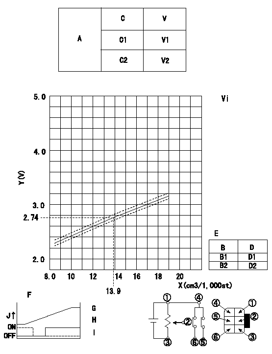
Adjustment of the potentiometer
* Measure the injection quantity at N = N1r/min with the control lever position C3 (equivalent to L1 mm).
Determine the voltage with the conversion formula and adjust the potentiometer.
Voltage conversion formula: V+-0.03 = xQ + y (V)
A:Performance standards for the potentiometer
B:Conversion point
C:Position of the control lever
D:Lever opening (from idle)
E:Standards for the potentiometer's ON/OFF switch
Vi:Applied voltage
V:Potentiometer voltage
X:Injection quantity: Q
Y:Voltage
N1:Pump speed
C3:Position of the control lever
L1:Thickness of the shim
C1:Idle
C2:Full-speed
B1:ON-->OFF
B2:OFF-->ON
F:Connecting diagram for the potentiometer
G:Output when (2) and (3) connected.
H:When (4) or (6) connected: switch OFF to ON.
I:When (4) or (5) connected: switch ON to OFF.
J:Output
----------
x=0.073 y=1.727 N1=600r/min C3=7deg L1=4.6mm Vi=10V
----------
V1=Above 0.2V V2=Below 9.6V Vi=10V D1=5+-3deg D2=Above 21.5deg
----------
x=0.073 y=1.727 N1=600r/min C3=7deg L1=4.6mm Vi=10V
----------
V1=Above 0.2V V2=Below 9.6V Vi=10V D1=5+-3deg D2=Above 21.5deg
0000001901 M-CSD ADJUSTMENT
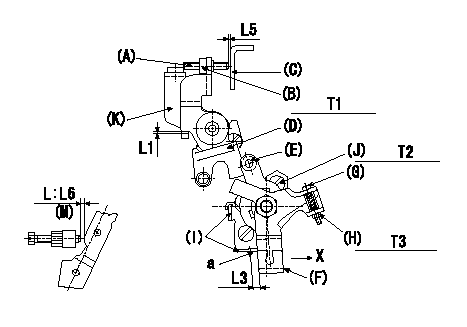
M-CSD adjustment
1. Fixing intermediate lever screw (A) [roller (E) must not contact intermediate lever (D)]
(1)Hold the control lever (C) in the idle position.
(2)Insert a block gauge (thickness gauge) L1 between the intermediate lever D and the intermediate lever bracket K and fix intermediate lever D.
(3)At this time, adjust screw (A) so that it is horizontal and the clearance between screw (A) and the control lever (C) is L2. Then, fix using nut (B).
2. Fixing the M-CSD stopper (I)
(1)At roller holder advance angle '0' adjust the lever shaft ball pin so that it contacts the roller holder.
(2)At this time, fix the stopper I using the screw J where the distance a between the CSD lever F and the stopper is L3.
(3)Pull the CSD lever F in the direction X until it contacts the stopper I and confirm that the timer stroke is L4.
3. Screw G adjustment (without a block gauge L3 at a)
(1)Adjust screw G so that the distance between screw A adjusted above in 1 and the control lever is above L5, then fix using nut H.
(2)Confirm that the control lever shim thickness is L6.
(M) = shim thickness
L = dimension L
----------
L1=1.5mm L2=1mm L3=Approx. 4.5mm L4=1.23+-0.2mm L5=Above1mm L6=7.2+-0.5mm
----------
T1=6~9N-m(0.6~0.9kgf-m) T2=5~7N-m(0.5~0.7kgf-m) T3=2~3N-m(0.2~0.3kgf-m) L1=1.5mm L3=Approx. 4.5mm L5=Above 1mm L6=7.2+-0.5mm
----------
L1=1.5mm L2=1mm L3=Approx. 4.5mm L4=1.23+-0.2mm L5=Above1mm L6=7.2+-0.5mm
----------
T1=6~9N-m(0.6~0.9kgf-m) T2=5~7N-m(0.5~0.7kgf-m) T3=2~3N-m(0.2~0.3kgf-m) L1=1.5mm L3=Approx. 4.5mm L5=Above 1mm L6=7.2+-0.5mm
Have questions with 104740-2460?
Group cross 104740-2460 ZEXEL
Nissan
Nissan
Nissan
Nissan
Nissan
Nissan
Nissan
Nissan
104740-2460
INJECTION-PUMP ASSEMBLY