
Rating:
Information injection-pump assembly
ZEXEL
104740-2340
1047402340
Cross reference number
ZEXEL
104740-2340
1047402340
Zexel num
Bosch num
Firm num
Name
104740-2340
INJECTION-PUMP ASSEMBLY
Calibration Data:
Adjustment conditions
Test oil
1404 Test oil ISO4113orSAEJ967d
1404 Test oil ISO4113orSAEJ967d
Test oil temperature
degC
45
45
50
Nozzle
105780-0060
Bosch type code
NP-DN0SD1510
Nozzle holder
105780-2150
Opening pressure
MPa
13
13
13.3
Opening pressure
kgf/cm2
133
133
136
Injection pipe
157805-7320
Injection pipe
Inside diameter - outside diameter - length (mm) mm 2-6-450
Inside diameter - outside diameter - length (mm) mm 2-6-450
Joint assembly
157641-4720
Tube assembly
157641-4020
Transfer pump pressure
kPa
20
20
20
Transfer pump pressure
kgf/cm2
0.2
0.2
0.2
Direction of rotation (viewed from drive side)
Left L
Left L
Injection timing adjustment
Pump speed
r/min
1400
1400
1400
Average injection quantity
mm3/st.
37.2
36.8
37.6
Difference in delivery
mm3/st.
3
Basic
*
Oil temperature
degC
50
48
52
Injection timing adjustment_02
Pump speed
r/min
600
600
600
Average injection quantity
mm3/st.
33.1
30.6
35.6
Oil temperature
degC
50
48
52
Injection timing adjustment_03
Pump speed
r/min
1000
1000
1000
Average injection quantity
mm3/st.
33.3
30.8
35.8
Oil temperature
degC
50
48
52
Injection timing adjustment_04
Pump speed
r/min
1400
1400
1400
Average injection quantity
mm3/st.
37.2
36.2
38.2
Difference in delivery
mm3/st.
3.5
Basic
*
Oil temperature
degC
50
48
52
Injection timing adjustment_05
Pump speed
r/min
1800
1800
1800
Average injection quantity
mm3/st.
37.3
35.3
39.3
Oil temperature
degC
50
48
52
Injection timing adjustment_06
Pump speed
r/min
2400
2400
2400
Average injection quantity
mm3/st.
37.5
35
40
Oil temperature
degC
52
50
54
Injection quantity adjustment
Pump speed
r/min
2700
2700
2700
Average injection quantity
mm3/st.
14
12
16
Difference in delivery
mm3/st.
4.5
Basic
*
Oil temperature
degC
55
52
58
Injection quantity adjustment_02
Pump speed
r/min
2700
2700
2700
Average injection quantity
mm3/st.
14
10.5
17.5
Difference in delivery
mm3/st.
5
Basic
*
Oil temperature
degC
55
52
58
Injection quantity adjustment_03
Pump speed
r/min
2800
2800
2800
Average injection quantity
mm3/st.
5
Oil temperature
degC
55
52
58
Governor adjustment
Pump speed
r/min
350
350
350
Average injection quantity
mm3/st.
10.5
9.5
11.5
Difference in delivery
mm3/st.
2
Basic
*
Oil temperature
degC
48
46
50
Governor adjustment_02
Pump speed
r/min
350
350
350
Average injection quantity
mm3/st.
10.5
8.5
12.5
Difference in delivery
mm3/st.
2.5
Basic
*
Oil temperature
degC
48
46
50
Governor adjustment_03
Pump speed
r/min
700
700
700
Average injection quantity
mm3/st.
5
Oil temperature
degC
50
48
52
Boost compensator adjustment
Pump speed
r/min
700
700
700
Average injection quantity
mm3/st.
16
9.5
22.5
Oil temperature
degC
50
48
52
Lever angle (shim thickness)
mm
7.2
7.2
7.2
Boost compensator adjustment_02
Pump speed
r/min
900
900
900
Average injection quantity
mm3/st.
11.6
4.6
18.6
Oil temperature
degC
50
48
52
Lever angle (shim thickness)
mm
7.2
7.2
7.2
Timer adjustment
Pump speed
r/min
100
100
100
Average injection quantity
mm3/st.
60
50
70
Basic
*
Oil temperature
degC
48
46
50
Remarks
Full
Full
Timer adjustment_02
Pump speed
r/min
100
100
100
Average injection quantity
mm3/st.
60
50
70
Oil temperature
degC
48
46
50
Speed control lever angle
Pump speed
r/min
350
350
350
Average injection quantity
mm3/st.
0
0
0
Oil temperature
degC
48
46
50
Remarks
Magnet OFF at idling position
Magnet OFF at idling position
0000000901
Pump speed
r/min
1000
1000
1000
Overflow quantity
cm3/min
390
260
520
Oil temperature
degC
50
48
52
Stop lever angle
Pump speed
r/min
1000
1000
1000
Pressure
kPa
422
393
451
Pressure
kgf/cm2
4.3
4
4.6
Basic
*
Oil temperature
degC
50
48
52
Stop lever angle_02
Pump speed
r/min
1000
1000
1000
Pressure
kPa
421.5
382
461
Pressure
kgf/cm2
4.3
3.9
4.7
Basic
*
Oil temperature
degC
50
48
52
Stop lever angle_03
Pump speed
r/min
1800
1800
1800
Pressure
kPa
588.5
549
628
Pressure
kgf/cm2
6
5.6
6.4
Oil temperature
degC
50
48
52
Stop lever angle_04
Pump speed
r/min
2400
2400
2400
Pressure
kPa
726
677
775
Pressure
kgf/cm2
7.4
6.9
7.9
Oil temperature
degC
52
50
54
0000001101
Pump speed
r/min
1000
1000
1000
Timer stroke
mm
3
2.8
3.2
Basic
*
Oil temperature
degC
50
48
52
_02
Pump speed
r/min
1000
1000
1000
Timer stroke
mm
3
2.7
3.3
Basic
*
Oil temperature
degC
50
48
52
_03
Pump speed
r/min
1800
1800
1800
Timer stroke
mm
7
6.5
7.5
Oil temperature
degC
50
48
52
_04
Pump speed
r/min
2400
2400
2400
Timer stroke
mm
9.35
8.9
9.8
Oil temperature
degC
52
50
54
0000001201
Max. applied voltage
V
8
8
8
Test voltage
V
13
12
14
Timing setting
K dimension
mm
3.3
3.2
3.4
KF dimension
mm
6.78
6.68
6.88
MS dimension
mm
0.8
0.7
0.9
Control lever angle alpha
deg.
25
23
27
Control lever angle beta
deg.
44
39
49
Test data Ex:
0000001801 POTENTIOMETER ADJUSTMENT
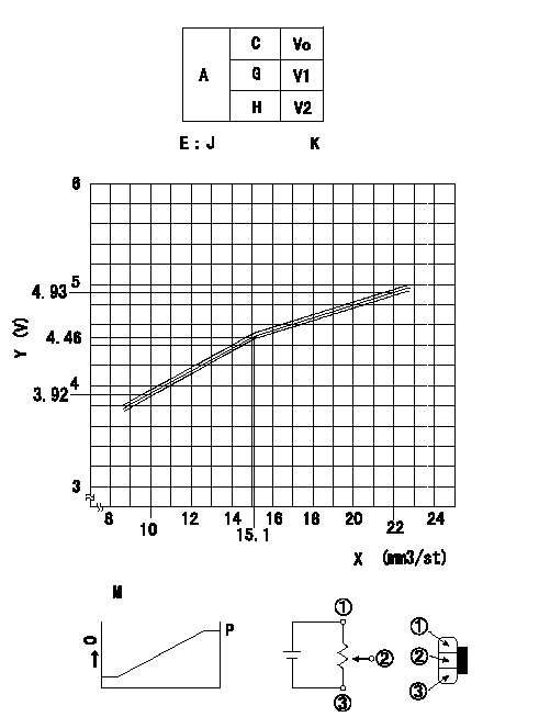
Adjustment of the potentiometer
At pump speed N and with the control lever angle at a from the idle position (clearance L), convert the injection quantity obtained to a voltage value using the graph and adjust the potentiometer.
Vo:Output voltage
Q:Injection quantity
A:Performance standards
C:Position of the control lever
G:Idle
H:Full speed
E:J = formula V+-0.03 = 0.1065Q+2.8519 (Q < 15.2 mm3/st)
V+-0.03 = 0.0674Q + 3.4462 (Q>=15.2 (mm3/st)
K = Vi: applied voltage
X:Injection quantity (mm3/st)
Y:Voltage (V)
M:Connecting diagram for the potentiometer
O:Output
P:Output when (2) and (3) connected.
----------
N=700(r/min) a=11(deg) L=7.2(mm) Vi=10(V)
----------
V1=0.5++(V) V2=-
----------
N=700(r/min) a=11(deg) L=7.2(mm) Vi=10(V)
----------
V1=0.5++(V) V2=-
0000001901 M-CSD ADJUSTMENT
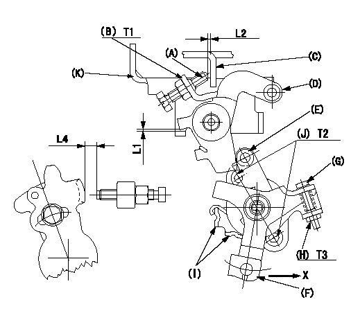
M-CSD adjustment
1. Fixing intermediate lever screw (A) [roller (E) must not contact intermediate lever (D)]
(1)Hold the control lever (C) in the idle position.
(2)Insert a block gauge (thickness gauge) L1 between the intermediate lever (D) and the bracket (K). Adjust screw (A) so that the distance between screw A and the control lever to L2 and fix using the nut (B).
2. Fixing the M-CSD stopper (I)
Pull the CSD lever F in the direction X until it contacts the stopper I and tighten the socket head bolt J when the timer stroke is L3.
3. Screw (G) adjustment
Pull the CSD lever F in the direction X until it contacts the stopper I and adjust using screw G so that the control lever shim thickness is L4. Then fix using nut H.
----------
L1=1+-0.1(mm) L2=1~2(mm) L3=0.82+-0.2(mm) L4=7.1+-0.5(mm)
----------
L1=1+-0.1(mm) L2=1~2(mm) L4=7.1+-0.5(mm) T1=5.9~8.8(N-m)(0.6~0.9(kgf-m)) T2=4.9~6.9(N-m)(0.5~0.7(kgf-m)) T3=2.0~2.9(N-m)(0.2~0.3(kgf-m))
----------
L1=1+-0.1(mm) L2=1~2(mm) L3=0.82+-0.2(mm) L4=7.1+-0.5(mm)
----------
L1=1+-0.1(mm) L2=1~2(mm) L4=7.1+-0.5(mm) T1=5.9~8.8(N-m)(0.6~0.9(kgf-m)) T2=4.9~6.9(N-m)(0.5~0.7(kgf-m)) T3=2.0~2.9(N-m)(0.2~0.3(kgf-m))
0000002001 DASHPOT ADJUSTMENT
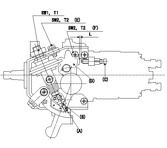
Adjustment of the dash pot
1. Insert a block gauge L (thickness gauge) between the idle set screw (C) and the control lever (D).
2. In the above condition, adjust so that the dashpot adjusting screw (A) contacts the pushrod. Then, fix using the locknut (B) (Tightening torque T3).
3. Confirm that the control lever returns to the idling position without the adjusting screw or dashpot sticking or coming loose.
(E) 5 locations
(F) 4 locations
----------
L=6.0+-0.05(mm) T3=4.9~6.9(N-m)(0.5~0.7(kgf-m))
----------
SW1=22(mm) SW2=10(mm) T1=14.7~19.6(N-m)(1.5~2.0(kgf-m)) T2=5.9~8.8(N-m)(0.6~0.9(kgf-m)) L=6.0+-0.05(mm)
----------
L=6.0+-0.05(mm) T3=4.9~6.9(N-m)(0.5~0.7(kgf-m))
----------
SW1=22(mm) SW2=10(mm) T1=14.7~19.6(N-m)(1.5~2.0(kgf-m)) T2=5.9~8.8(N-m)(0.6~0.9(kgf-m)) L=6.0+-0.05(mm)
Have questions with 104740-2340?
Group cross 104740-2340 ZEXEL
104740-2340
INJECTION-PUMP ASSEMBLY