
Rating:
Information injection-pump assembly
ZEXEL
104740-2040
1047402040
Cross reference number
ZEXEL
104740-2040
1047402040
Zexel num
Bosch num
Firm num
Name
Calibration Data:
Adjustment conditions
Test oil
1404 Test oil ISO4113orSAEJ967d
1404 Test oil ISO4113orSAEJ967d
Test oil temperature
degC
45
45
50
Nozzle
105000-2010
Bosch type code
NP-DN12SD12TT
Nozzle holder
105780-2080
Opening pressure
MPa
14.7
14.7
15.19
Opening pressure
kgf/cm2
150
150
155
Injection pipe
Inside diameter - outside diameter - length (mm) mm 2-6-840
Inside diameter - outside diameter - length (mm) mm 2-6-840
Transfer pump pressure
kPa
20
20
20
Transfer pump pressure
kgf/cm2
0.2
0.2
0.2
Direction of rotation (viewed from drive side)
Right R
Right R
Injection timing adjustment
Pump speed
r/min
600
600
600
Boost pressure
kPa
0
0
0
Boost pressure
mmHg
0
0
0
Average injection quantity
mm3/st.
30.4
29.9
30.9
Difference in delivery
mm3/st.
2.5
Basic
*
Injection timing adjustment_02
Pump speed
r/min
2700
2700
2700
Boost pressure
kPa
68
66.7
69.3
Boost pressure
mmHg
510
500
520
Average injection quantity
mm3/st.
9.7
6.2
13.2
Injection timing adjustment_03
Pump speed
r/min
2200
2200
2200
Boost pressure
kPa
68
66.7
69.3
Boost pressure
mmHg
510
500
520
Average injection quantity
mm3/st.
37.5
35
40
Injection timing adjustment_04
Pump speed
r/min
900
900
900
Boost pressure
kPa
34
32.7
35.3
Boost pressure
mmHg
255
245
265
Average injection quantity
mm3/st.
37.5
36.5
38.5
Injection timing adjustment_05
Pump speed
r/min
600
600
600
Boost pressure
kPa
0
0
0
Boost pressure
mmHg
0
0
0
Average injection quantity
mm3/st.
30.4
29.4
31.4
Injection quantity adjustment
Pump speed
r/min
2700
2700
2700
Boost pressure
kPa
68
66.7
69.3
Boost pressure
mmHg
510
500
520
Average injection quantity
mm3/st.
9.7
6.7
12.7
Basic
*
Injection quantity adjustment_02
Pump speed
r/min
2800
2800
2800
Boost pressure
kPa
68
66.7
69.3
Boost pressure
mmHg
510
500
520
Average injection quantity
mm3/st.
6
Governor adjustment
Pump speed
r/min
325
325
325
Boost pressure
kPa
0
0
0
Boost pressure
mmHg
0
0
0
Average injection quantity
mm3/st.
6
4.5
7.5
Difference in delivery
mm3/st.
3
Basic
*
Governor adjustment_02
Pump speed
r/min
325
325
325
Boost pressure
kPa
0
0
0
Boost pressure
mmHg
0
0
0
Average injection quantity
mm3/st.
6
4
8
Boost compensator adjustment
Pump speed
r/min
900
900
900
Boost pressure
kPa
34
32.7
35.3
Boost pressure
mmHg
255
245
265
Average injection quantity
mm3/st.
12
7
17
Timer adjustment
Pump speed
r/min
100
100
100
Boost pressure
kPa
0
0
0
Boost pressure
mmHg
0
0
0
Average injection quantity
mm3/st.
45
40
50
Basic
*
Speed control lever angle
Pump speed
r/min
325
325
325
Boost pressure
kPa
0
0
0
Boost pressure
mmHg
0
0
0
Average injection quantity
mm3/st.
0
0
0
Remarks
Magnet OFF
Magnet OFF
0000000901
Pump speed
r/min
1000
1000
1000
Overflow quantity
cm3/min
348
216
480
Stop lever angle
Pump speed
r/min
900
900
900
Boost pressure
kPa
34
32.7
35.3
Boost pressure
mmHg
255
245
265
Pressure
kPa
313.5
284
343
Pressure
kgf/cm2
3.2
2.9
3.5
Basic
*
Stop lever angle_02
Pump speed
r/min
900
900
900
Boost pressure
kPa
34
32.7
35.3
Boost pressure
mmHg
255
245
265
Pressure
kPa
313.5
284
343
Pressure
kgf/cm2
3.2
2.8
3.6
Stop lever angle_03
Pump speed
r/min
1200
1200
1200
Boost pressure
kPa
34
32.7
35.3
Boost pressure
mmHg
255
245
265
Pressure
kPa
372.5
333
412
Pressure
kgf/cm2
3.8
3.4
4.2
Stop lever angle_04
Pump speed
r/min
2400
2400
2400
Boost pressure
kPa
34
32.7
35.3
Boost pressure
mmHg
255
245
265
Pressure
kPa
676.5
637
716
Pressure
kgf/cm2
6.9
6.5
7.3
0000001101
Pump speed
r/min
900
900
900
Boost pressure
kPa
34
32.7
35.3
Boost pressure
mmHg
255
245
265
Timer stroke
mm
2.6
2.3
2.9
Basic
*
_02
Pump speed
r/min
900
900
900
Boost pressure
kPa
34
32.7
35.3
Boost pressure
mmHg
255
245
265
Timer stroke
mm
2.6
2.2
3
_03
Pump speed
r/min
1200
1200
1200
Boost pressure
kPa
34
32.7
35.3
Boost pressure
mmHg
255
245
265
Timer stroke
mm
4.2
3.6
4.8
_04
Pump speed
r/min
2400
2400
2400
Boost pressure
kPa
34
32.7
35.3
Boost pressure
mmHg
255
245
265
Timer stroke
mm
9.35
8.9
9.8
0000001201
Max. applied voltage
V
8
8
8
Test voltage
V
13
12
14
Timing setting
K dimension
mm
3.3
3.2
3.4
KF dimension
mm
5.75
5.65
5.85
MS dimension
mm
0.5
0.4
0.6
BCS stroke
mm
4
3.9
4.1
Control lever angle alpha
deg.
25
21
29
Control lever angle beta
deg.
41
36
46
Control lever angle gamma
deg.
11
10.5
11.5
Test data Ex:
0000001801 W-CSD ADJUSTMENT
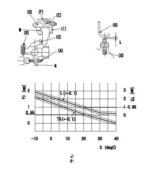
Adjustment of the W-CSD
1. Adjustment of the advance angle of the timer
(1)Determine the timer advance angle from the graph in the figure.
(2)(1) Adjust with the screw (A) so that the timer advance angle determined in the item (1) is obtained.
2. Setting the intermediate lever position
(1)Insert a block gauge L1 = L between the idling set screw (G) and the stopper (H).
(2)When the intermediate lever is perpendicular, fix it so that it contacts the control lever (F).
(3)Align lever (D) perpendicular to the aligning mark.
3. W-CSD lever adjustment
(1)Insert a block gauge L2 determined from the graph (L-t) in the figure between the idling set screw (G) and the stopper (H).
(2)Fix screw (B) so that the W-CSD lever (C)'s roller contacts the intermediate lever (D).
Note:
When inserting the block gauge, separate lever (C) and (D) using screw (B) to prevent excessive force on the lever.
X = temperature t (deg C)
Y1 = timer lift TA (mm)
Y2 = control lever dimension L mm (control lever position
J = graph L - t
P = graph TA - t:
K = intermediate lever perpendicular position
M = aligning mark
----------
L1=0.9+-0.05mm L2=L1+-0.05mm
----------
L1=0.9+-0.05mm J=-10<=t(degC)<=20 L=-0.0467t+2.253 20<=t(degC)<=30 L=-0.0553t+2.0664 30<=t(degC)<=40 L=-0.0148t+0.8505 P=-10<=t(degC)<=20 TA=-0.0367t+1.284 20<=t(degC)<=40 TA=-0.0275t+1.1
----------
L1=0.9+-0.05mm L2=L1+-0.05mm
----------
L1=0.9+-0.05mm J=-10<=t(degC)<=20 L=-0.0467t+2.253 20<=t(degC)<=30 L=-0.0553t+2.0664 30<=t(degC)<=40 L=-0.0148t+0.8505 P=-10<=t(degC)<=20 TA=-0.0367t+1.284 20<=t(degC)<=40 TA=-0.0275t+1.1
0000001901 DASHPOT ADJUSTMENT
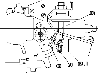
Adjustment of the dash pot
1. Insert a block gauge L1 (thickness gauge) between the idle set screw and the bracket.
2. In the above condition, adjust the elongated hole so that the pushrod contacts the control lever. Then, fix using the bolt.
TT
Note:
(1)The dashpot and control lever contact faces must be smooth.
(2)Confirm that the control lever returns to the idling position.
----------
L1=3.8+-0.05mm T=6~9N-m{0.6~0.9kgf-m}
----------
L1=3.8+-0.05mm T=6~9N-m{0.6~0.9kgf-m}
----------
L1=3.8+-0.05mm T=6~9N-m{0.6~0.9kgf-m}
----------
L1=3.8+-0.05mm T=6~9N-m{0.6~0.9kgf-m}
0000002001 STARTING I/Q ADJUSTMENT
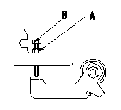
Starting injection quantity adjustment
Fix the stop lever's starting injection quantity adjusting bolt. At adjustment, adjust the bolt so that the starting injection quantity is as specified and then fix using the locknut.
A = locknut
B = adjusting bolt
----------
----------
----------
----------