Rating:
Information injection-pump assembly
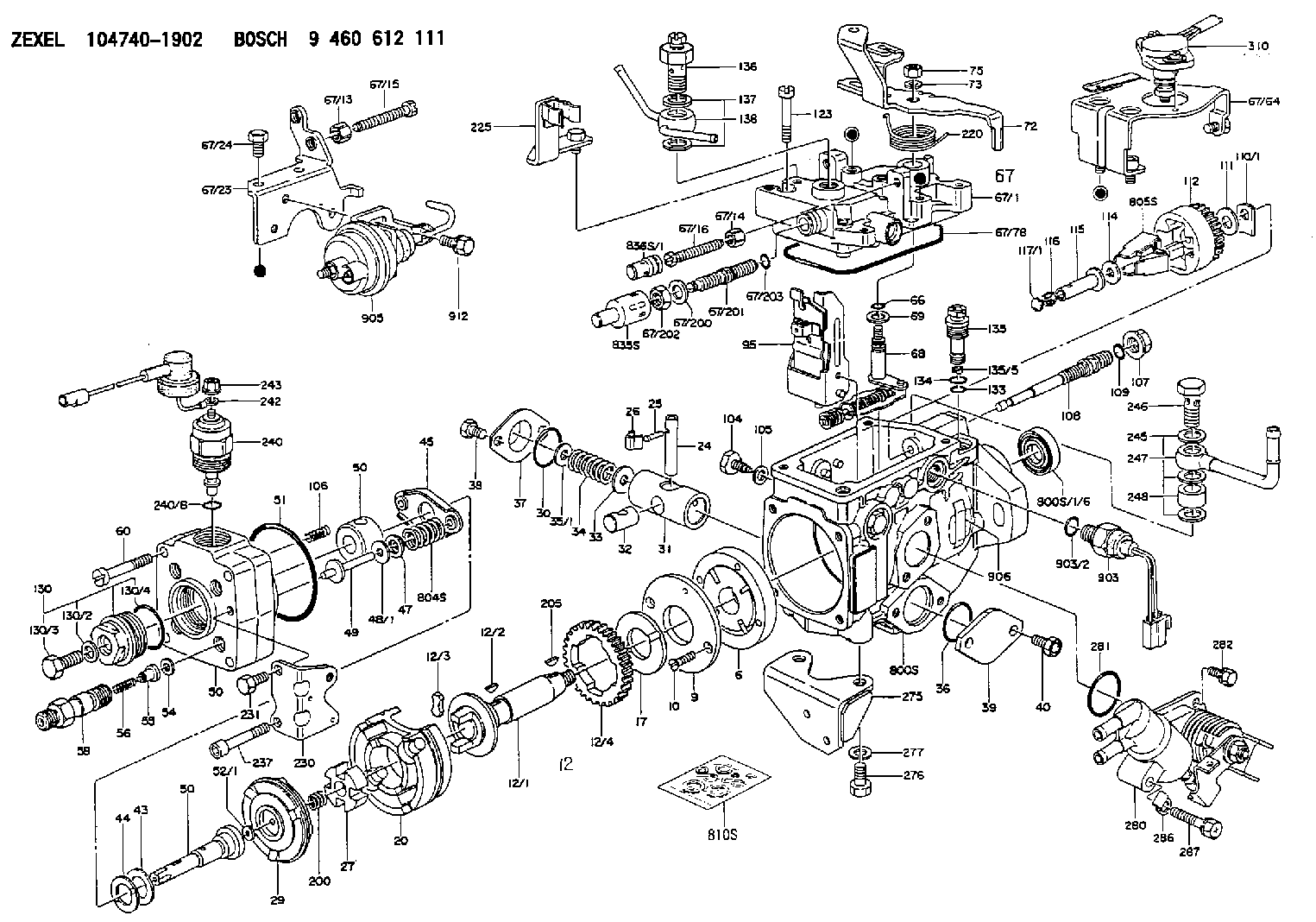
BOSCH
9 460 612 111
9460612111
ZEXEL
104740-1902
1047401902
Components :
| 0. | INJECTION-PUMP ASSEMBLY | 104740-1902 |
| 1. | _ | |
| 2. | FUEL INJECTION PUMP | 104640-1902 |
| 3. | NUMBER PLATE | 146921-2800 |
| 4. | _ | 146672-5820 |
| 5. | CAPSULE | |
| 6. | ADJUSTING DEVICE | 146620-4720 |
| 7. | NOZZLE AND HOLDER ASSY | 105158-2182 |
| 8. | Nozzle and Holder | 8-94470-499-1 |
| 9. | Open Pre:MPa(Kqf/cm2) | 13.2{135} |
| 10. | NOZZLE-HOLDER | 105088-1090 |
| 11. | NOZZLE | 105007-1100 |
Scheme ###:
| 1/6. | [1] | 146601-0700 | PACKING RING |
| 6. | [1] | 146100-0120 | SUPPLY PUMP |
| 9. | [1] | 146103-0000 | COVER |
| 10. | [2] | 139104-0000 | FLAT-HEAD SCREW |
| 12. | [1] | 146200-0320 | DRIVE SHAFT |
| 12/1. | [1] | 146200-0300 | DRIVE SHAFT |
| 12/2. | [1] | 146201-0000 | WOODRUFF KEY |
| 12/3. | [2] | 146202-0100 | DAMPER |
| 12/4. | [1] | 146203-0000 | TOOTHED GEAR |
| 17. | [1] | 146204-0000 | PLAIN WASHER |
| 20. | [1] | 146210-1920 | ROLLER SET |
| 24. | [1] | 146303-0100 | BEARING PIN |
| 25. | [1] | 146304-0000 | BEARING PIN |
| 26. | [1] | 146305-0000 | CLAMPING BAND |
| 27. | [1] | 146205-0000 | SLOTTED WASHER |
| 29. | [1] | 146220-0020 | CAM PLATE |
| 30. | [1] | 146600-0800 | O-RING |
| 31. | [1] | 146300-0500 | PUMP PLUNGER |
| 32. | [1] | 146301-0000 | SLIDING PIECE |
| 33. | [1] | 146603-0700 | SHIM D17.5&7.5T0.60 |
| 34. | [1] | 146302-8400 | COMPRESSION SPRING |
| 34B. | [1] | 146302-9600 | COMPRESSION SPRING |
| 34C. | [1] | 146302-9700 | COMPRESSION SPRING |
| 35/1. | [0] | 146603-0700 | SHIM D17.5&7.5T0.60 |
| 35/1. | [0] | 146603-0800 | SHIM D17.5&7.5T0.70 |
| 35/1. | [0] | 146603-0900 | SHIM D17.5&7.5T0.90 |
| 35/1. | [0] | 146603-1000 | SHIM D17.5&7.5T1.00 |
| 35/1. | [0] | 146603-1100 | SHIM D17.5&7.5T1.20 |
| 35/1. | [0] | 146603-3600 | SHIM D17.5&7.5T2.40 |
| 36. | [1] | 146600-0800 | O-RING |
| 37. | [1] | 146310-0700 | COVER |
| 38. | [2] | 146620-5000 | BLEEDER SCREW |
| 39. | [1] | 146310-0100 | COVER |
| 40. | [2] | 146620-5000 | BLEEDER SCREW |
| 43. | [1] | 146230-0000 | SHIM |
| 44. | [1] | 146230-0100 | PLAIN WASHER |
| 45. | [1] | 146231-0001 | SLOTTED WASHER |
| 47. | [2] | 146233-0000 | SLOTTED WASHER |
| 48/1. | [1] | 146603-0000 | SHIM D17.0&5.2T0.50 |
| 48/1. | [1] | 146603-0100 | SHIM D17.0&5.2T0.80 |
| 48/1. | [1] | 146603-0200 | SHIM D17.0&5.2T1.00 |
| 48/1. | [1] | 146603-0300 | SHIM D17.0&5.2T1.20 |
| 48/1. | [1] | 146603-0400 | SHIM D17.0&5.2T1.50 |
| 48/1. | [1] | 146603-0500 | SHIM D17.0&5.2T1.80 |
| 48/1. | [1] | 146603-0600 | SHIM D17.0&5.2T2.00 |
| 48/1. | [1] | 146690-1400 | SHIM D17&5.2T0.9 |
| 48/1. | [1] | 146690-1500 | SHIM D17&5.2T1.1 |
| 48/1. | [1] | 146690-1600 | SHIM D17&5.2T1.3 |
| 48/1. | [1] | 146690-1700 | SHIM D17&5.2T1.4 |
| 48/1. | [1] | 146690-1800 | SHIM D17&5.2T1.6 |
| 48/1. | [1] | 146690-1900 | SHIM D17&5.2T1.7 |
| 48/1. | [1] | 146690-5800 | SHIM |
| 48/1. | [1] | 146690-5900 | SHIM |
| 48/1. | [1] | 146690-6000 | SHIM |
| 48/1. | [1] | 146690-6100 | SHIM |
| 48/1. | [1] | 146690-6200 | SHIM |
| 48/1. | [1] | 146690-6300 | SHIM |
| 48/1. | [1] | 146690-6400 | SHIM |
| 48/1. | [1] | 146690-6500 | SHIM |
| 48/1. | [1] | 146690-6600 | SHIM |
| 48/1. | [1] | 146690-6700 | SHIM |
| 48/1. | [1] | 146690-6800 | SHIM |
| 48/1. | [1] | 146690-6900 | SHIM |
| 48/1. | [1] | 146690-7000 | SHIM |
| 48/1. | [1] | 146690-7100 | SHIM |
| 48/1. | [1] | 146690-7200 | SHIM |
| 48/1. | [1] | 146690-7300 | SHIM |
| 48/1. | [1] | 146690-7400 | SHIM |
| 48/1. | [1] | 146690-7500 | SHIM |
| 48/1. | [1] | 146690-7800 | SHIM |
| 49. | [2] | 146234-0020 | GUIDE PIN |
| 50. | [1] | 146401-2020 | HYDRAULIC HEAD |
| 50. | [1] | 146401-2020 | HYDRAULIC HEAD |
| 50. | [1] | 146401-2020 | HYDRAULIC HEAD |
| 51. | [1] | 146600-0000 | O-RING |
| 52/1. | [1] | 146420-0000 | SHIM D9.5&3.0T1.90 |
| 52/1. | [1] | 146420-0100 | SHIM D9.5&3.0T1.92 |
| 52/1. | [1] | 146420-0200 | SHIM D9.5&3.0T1.94 |
| 52/1. | [1] | 146420-0300 | SHIM D9.5&3.0T1.96 |
| 52/1. | [1] | 146420-0400 | SHIM D9.5&3.0T1.98 |
| 52/1. | [1] | 146420-0500 | SHIM D9.5&3.0T2.00 |
| 52/1. | [1] | 146420-0600 | SHIM D9.5&3.0T2.02 |
| 52/1. | [1] | 146420-0700 | SHIM D9.5&3.0T2.04 |
| 52/1. | [1] | 146420-0800 | SHIM D9.5&3.0T2.06 |
| 52/1. | [1] | 146420-0900 | SHIM D9.5&3.0T2.08 |
| 52/1. | [1] | 146420-1000 | SHIM D9.5&3.0T2.10 |
| 52/1. | [1] | 146420-1100 | SHIM D9.5&3.0T2.12 |
| 52/1. | [1] | 146420-1200 | SHIM D9.5&3.0T2.14 |
| 52/1. | [1] | 146420-1300 | SHIM D9.5&3.0T2.16 |
| 52/1. | [1] | 146420-1400 | SHIM D9.5&3.0T2.18 |
| 52/1. | [1] | 146420-1500 | SHIM D9.5&3.0T2.20 |
| 52/1. | [1] | 146420-1600 | SHIM D9.5&3.0T2.22 |
| 52/1. | [1] | 146420-1700 | SHIM D9.5&3.0T2.24 |
| 52/1. | [1] | 146420-1800 | SHIM D9.5&3.0T2.26 |
| 52/1. | [1] | 146420-1900 | SHIM D9.5&3.0T2.28 |
| 52/1. | [1] | 146420-2000 | SHIM D9.5&3.0T2.30 |
| 52/1. | [1] | 146420-2100 | SHIM D9.5&3.0T2.32 |
| 52/1. | [1] | 146420-2200 | SHIM D9.5&3.0T2.34 |
| 52/1. | [1] | 146420-2300 | SHIM D9.5&3.0T2.36 |
| 52/1. | [1] | 146420-2400 | SHIM D9.5&3.0T2.38 |
| 52/1. | [1] | 146420-2500 | SHIM D9.5&3.0T2.40 |
| 52/1. | [1] | 146420-2600 | SHIM D9.5&3.0T2.42 |
| 52/1. | [1] | 146420-2700 | SHIM D9.5&3.0T2.44 |
| 52/1. | [1] | 146420-2800 | SHIM D9.5&3.0T2.46 |
| 52/1. | [1] | 146420-2900 | SHIM D9.5&3.0T2.48 |
| 52/1. | [1] | 146420-3000 | SHIM D9.5&3.0T2.50 |
| 52/1. | [1] | 146420-3100 | SHIM D9.5&3.0T2.52 |
| 52/1. | [1] | 146420-3200 | SHIM D9.5&3.0T2.54 |
| 52/1. | [1] | 146420-3300 | SHIM D9.5&3.0T2.56 |
| 52/1. | [1] | 146420-3400 | SHIM D9.5&3.0T2.58 |
| 52/1. | [1] | 146420-3500 | SHIM D9.5&3.0T2.60 |
| 52/1. | [1] | 146420-3600 | SHIM D9.5&3.0T2.62 |
| 52/1. | [1] | 146420-3700 | SHIM D9.5&3.0T2.64 |
| 52/1. | [1] | 146420-3800 | SHIM D9.5&3.0T2.66 |
| 52/1. | [1] | 146420-3900 | SHIM D9.5&3.0T2.68 |
| 52/1. | [1] | 146420-4000 | SHIM D9.5&3.0T2.70 |
| 52/1. | [1] | 146420-4100 | SHIM D9.5&3.0T2.72 |
| 52/1. | [1] | 146420-4200 | SHIM D9.5&3.0T2.74 |
| 52/1. | [1] | 146420-4300 | SHIM D9.5&3.0T2.76 |
| 52/1. | [1] | 146420-4400 | SHIM D9.5&3.0T2.78 |
| 52/1. | [1] | 146420-4500 | SHIM D9.5&3.0T2.80 |
| 52/1. | [1] | 146420-4600 | SHIM D9.5&3.0T2.82 |
| 52/1. | [1] | 146420-4700 | SHIM D9.5&3.0T2.84 |
| 52/1. | [1] | 146420-4800 | SHIM D9.5&3.0T2.86 |
| 52/1. | [1] | 146420-4900 | SHIM D9.5&3.0T2.88 |
| 52/1. | [1] | 146420-5000 | SHIM D9.5&3.0T2.90 |
| 52/1. | [1] | 146420-5100 | SHIM D9.5&3.0T1.74 |
| 52/1. | [1] | 146420-5200 | SHIM D9.5&3.0T1.76 |
| 52/1. | [1] | 146420-5300 | SHIM D9.5&3.0T1.78 |
| 52/1. | [1] | 146420-5400 | SHIM D9.5&3.0T1.80 |
| 52/1. | [1] | 146420-5500 | SHIM D9.5&3.0T1.82 |
| 52/1. | [1] | 146420-5600 | SHIM D9.5&3.0T1.84 |
| 52/1. | [1] | 146420-5700 | SHIM D9.5&3.0T1.86 |
| 52/1. | [1] | 146420-5800 | SHIM D9.5&3.0T1.88 |
| 54. | [4] | 146433-0100 | GASKET D12&6.4T1.00 |
| 55. | [4] | 146430-0120 | DELIVERY-VALVE ASSEMBLY |
| 56. | [4] | 146432-0000 | COMPRESSION SPRING |
| 58. | [4] | 146440-0120 | FITTING |
| 60. | [3] | 139106-0100 | FLAT-HEAD SCREW |
| 66. | [1] | 146600-0100 | O-RING |
| 67. | [1] | 146503-5720 | GOVERNOR COVER |
| 67/1. | [1] | 146505-8122 | GOVERNOR COVER |
| 67/13. | [1] | 146621-1700 | UNION NUT |
| 67/14. | [1] | 146621-1700 | UNION NUT |
| 67/15. | [1] | 146526-2800 | BLEEDER SCREW |
| 67/16. | [1] | 146526-2800 | BLEEDER SCREW |
| 67/23. | [1] | 146929-3400 | BRACKET |
| 67/24. | [2] | 139006-4700 | BLEEDER SCREW |
| 67/64. | [1] | 146928-8920 | BRACKET |
| 67/78. | [1] | 146600-1000 | SEAL RING |
| 67/200. | [1] | 139308-0300 | PLAIN WASHER |
| 67/201. | [1] | 146545-3400 | THREADED PIN L53.00 |
| 67/201B. | [1] | 146545-3500 | THREADED PIN L55.00 |
| 67/201C. | [1] | 146545-3600 | THREADED PIN L57.00 |
| 67/202. | [1] | 139208-0900 | UNION NUT |
| 67/203. | [1] | 146600-1200 | O-RING |
| 68. | [1] | 146514-1120 | CONTROL SHAFT |
| 69. | [1] | 139310-0200 | PLAIN WASHER |
| 72. | [1] | 146539-1820 | CONTROL LEVER |
| 72B. | [1] | 146539-1920 | CONTROL LEVER |
| 73. | [1] | 014110-6440 | LOCKING WASHER |
| 75. | [1] | 146621-2500 | UNION NUT |
| 95. | [1] | 146851-1220 | FULCRUM LEVER |
| 104. | [2] | 146568-0000 | SLOTTED SPRING PIN |
| 105. | [2] | 026508-1140 | GASKET D11.4&8.2T1 |
| 106. | [2] | 146588-0500 | COILED SPRING |
| 107. | [1] | 146569-0300 | UNION NUT |
| 108. | [1] | 146570-0420 | GOVERNOR SHAFT |
| 109. | [1] | 146600-0400 | O-RING |
| 110/1. | [1] | 146571-0000 | SHIM D20.2&8.3T1.05 |
| 110/1. | [1] | 146571-0100 | SHIM D20.2&8.3T1.25 |
| 110/1. | [1] | 146571-0200 | SHIM D20.2&8.3T1.45 |
| 110/1. | [1] | 146571-0300 | SHIM D20.2&8.3T1.65 |
| 110/1. | [1] | 146571-0400 | SHIM D20.2&8.3T1.85 |
| 110/1. | [1] | 146571-0500 | SHIM D20.2&8.3T1.15 |
| 110/1. | [1] | 146571-0600 | SHIM D20.2&8.3T1.35 |
| 110/1. | [1] | 146571-0700 | SHIM D20.2&8.3T1.55 |
| 110/1. | [1] | 146571-0800 | SHIM D20.2&8.3T1.75 |
| 111. | [1] | 146602-0600 | PLAIN WASHER D20&8.4T1.40 |
| 112. | [1] | 146572-0020 | FLYWEIGHT ASSEMBLY |
| 114. | [1] | 146602-0500 | PLAIN WASHER D17&6.4T1.60 |
| 115. | [1] | 146575-3200 | SLIDING SLEEVE |
| 116. | [1] | 146576-0000 | SEALING CAP |
| 117/1. | [1] | 146577-1800 | PLUG L2.10 |
| 117/1. | [1] | 146577-1900 | PLUG L2.30 |
| 117/1. | [1] | 146577-2000 | PLUG L2.50 |
| 117/1. | [1] | 146577-2100 | PLUG L2.70 |
| 117/1. | [1] | 146577-2200 | PLUG L2.90 |
| 117/1. | [1] | 146577-2300 | PLUG L3.10 |
| 117/1. | [1] | 146577-2400 | PLUG L3.30 |
| 117/1. | [1] | 146577-2500 | PLUG L3.50 |
| 117/1. | [1] | 146577-2600 | PLUG L3.70 |
| 117/1. | [1] | 146577-2700 | PLUG L3.90 |
| 117/1. | [1] | 146577-2800 | PLUG L4.10 |
| 117/1. | [1] | 146577-2900 | PLUG L4.30 |
| 117/1. | [1] | 146577-3000 | PLUG L4.50 |
| 117/1. | [1] | 146577-3100 | PLUG L4.70 |
| 117/1. | [1] | 146577-3200 | PLUG L4.90 |
| 117/1. | [1] | 146577-3300 | PLUG L5.10 |
| 117/1. | [1] | 146577-6700 | PLUG L2.2 |
| 117/1. | [1] | 146577-6800 | PLUG L2.4 |
| 117/1. | [1] | 146577-6900 | PLUG L2.6 |
| 117/1. | [1] | 146577-7000 | PLUG L2.8 |
| 117/1. | [1] | 146577-7100 | PLUG L3.0 |
| 117/1. | [1] | 146577-7200 | PLUG L3.2 |
| 117/1. | [1] | 146577-7300 | PLUG L3.4 |
| 117/1. | [1] | 146577-7400 | PLUG L3.6 |
| 117/1. | [1] | 146577-7500 | PLUG L3.8 |
| 117/1. | [1] | 146577-7600 | PLUG L4.0 |
| 117/1. | [1] | 146577-7700 | PLUG L4.2 |
| 117/1. | [1] | 146577-7800 | PLUG L4.4 |
| 117/1. | [1] | 146577-7900 | PLUG L4.6 |
| 117/1. | [1] | 146577-8000 | PLUG L4.8 |
| 117/1. | [1] | 146577-8100 | PLUG L5.0 |
| 117/1. | [1] | 146877-0000 | PLUG L5.2 |
| 117/1. | [1] | 146877-0100 | PLUG L5.3 |
| 117/1. | [1] | 146877-0200 | PLUG L5.4 |
| 117/1. | [1] | 146877-0300 | PLUG L5.5 |
| 117/1. | [1] | 146877-4700 | PLUG |
| 117/1. | [1] | 146877-4800 | PLUG |
| 117/1. | [1] | 146877-4900 | PLUG |
| 117/1. | [1] | 146877-5000 | PLUG |
| 123. | [4] | 139106-0200 | FLAT-HEAD SCREW |
| 130. | [1] | 146421-0020 | CAPSULE |
| 130/2. | [1] | 026508-1140 | GASKET D11.4&8.2T1 |
| 130/3. | [1] | 146422-0000 | BLEEDER SCREW |
| 130/4. | [1] | 146600-0500 | O-RING |
| 133. | [1] | 146600-0600 | O-RING |
| 134. | [1] | 146600-0700 | O-RING |
| 135. | [1] | 146110-0220 | CONTROL VALVE |
| 135/5. | [1] | 146114-0000 | SPRING WASHER |
| 136. | [1] | 146120-1020 | OVER FLOW VALVE |
| 137. | [2] | 026512-1840 | GASKET D17.9&12.2T1.50 |
| 138. | [1] | 146665-4720 | INLET UNION |
| 200. | [1] | 146206-0100 | COILED SPRING |
| 205. | [1] | 029470-4030 | WOODRUFF KEY |
| 220. | [1] | 146587-1100 | COILED SPRING |
| 225. | [1] | 146929-2620 | BRACKET |
| 230. | [1] | 146926-8600 | BRACKET |
| 231. | [1] | 139006-4800 | BLEEDER SCREW |
| 237. | [1] | 146620-0200 | HEX-SOCKET-HEAD CAP SCREW |
| 240. | [1] | 146650-1220 | PULLING ELECTROMAGNET |
| 240/8. | [1] | 146600-1700 | O-RING |
| 242. | [1] | 146658-9120 | WIRE |
| 243. | [1] | 146621-1000 | UNION NUT |
| 245. | [3] | 026512-1840 | GASKET D17.9&12.2T1.50 |
| 246. | [1] | 146125-0000 | EYE BOLT |
| 247. | [1] | 146606-6620 | INLET UNION |
| 248. | [1] | 146614-0200 | SPACER BUSHING |
| 275. | [1] | 146612-0120 | BRACKET |
| 276. | [2] | 010010-2040 | BLEEDER SCREW M10P1.5L20 |
| 277. | [2] | 014111-0440 | LOCKING WASHER |
| 280. | [1] | 146360-9620 | START ADVANCE ASSY |
| 281. | [1] | 146600-0800 | O-RING |
| 282. | [1] | 020306-1240 | BLEEDER SCREW |
| 286. | [1] | 146659-5200 | CLAMPING BAND |
| 287. | [1] | 020106-3540 | BLEEDER SCREW |
| 310. | [1] | 146683-2220 | POTENTCIOMETER |
| 800S. | [1] | 146019-5020 | PUMP HOUSING |
| 800S/1/6. | [1] | 146601-0700 | PACKING RING |
| 804S. | [1] | 146232-0320 | COMPRESSION SPRING |
| 805S. | [1] | 146574-0120 | PARTS SET |
| 810S. | [1] | 146600-1120 | REPAIR SET |
| 835S. | [1] | 146598-1000 | CAP |
| 836S/1. | [1] | 146598-0600 | CAP L18 |
| 836S/1. | [1] | 146598-0700 | CAP L21 |
| 836S/1. | [1] | 146598-0800 | CAP L24 |
| 836S/1. | [1] | 146598-0900 | CAP L27 |
| 903. | [1] | 146672-5820 | PULSE GENERATOR |
| 903/2. | [1] | 146600-1300 | O-RING &13W1.9 |
| 905. | [1] | 146620-4720 | ACTUATOR |
| 906. | [1] | 146921-2800 | NAMEPLATE |
| 912. | [2] | 020146-1270 | BLEEDER SCREW |
Include in #2:
104740-1902
as INJECTION-PUMP ASSEMBLY
Cross reference number
BOSCH
9 460 612 111
9460612111
ZEXEL
104740-1902
1047401902
Zexel num
Bosch num
Firm num
Name
Calibration Data:
Adjustment conditions
Test oil
1404 Test oil ISO4113orSAEJ967d
1404 Test oil ISO4113orSAEJ967d
Test oil temperature
degC
40
40
45
Nozzle
105780-0060
Bosch type code
NP-DN0SD1510
Nozzle holder
105780-2150
Opening pressure
MPa
13
13
13.3
Opening pressure
kgf/cm2
133
133
136
Injection pipe
157805-7320
Injection pipe
Inside diameter - outside diameter - length (mm) mm 2-6-450
Inside diameter - outside diameter - length (mm) mm 2-6-450
Joint assembly
157641-4720
Tube assembly
157641-4020
Transfer pump pressure
kPa
20
20
20
Transfer pump pressure
kgf/cm2
0.2
0.2
0.2
Direction of rotation (viewed from drive side)
Right R
Right R
Injection timing adjustment
Pump speed
r/min
1250
1250
1250
Average injection quantity
mm3/st.
49.1
48.1
50.1
Difference in delivery
mm3/st.
3.5
Basic
*
Injection timing adjustment_02
Pump speed
r/min
2500
2500
2500
Average injection quantity
mm3/st.
15.4
11.9
18.9
Injection timing adjustment_03
Pump speed
r/min
2150
2150
2150
Average injection quantity
mm3/st.
47.3
44.3
50.3
Injection timing adjustment_04
Pump speed
r/min
1250
1250
1250
Average injection quantity
mm3/st.
49.1
48.1
50.1
Injection timing adjustment_05
Pump speed
r/min
600
600
600
Average injection quantity
mm3/st.
50.7
47.7
53.7
Injection timing adjustment_06
Pump speed
r/min
500
500
500
Average injection quantity
mm3/st.
51.2
45.7
56.7
Injection quantity adjustment
Pump speed
r/min
2500
2500
2500
Average injection quantity
mm3/st.
15.4
11.9
18.9
Difference in delivery
mm3/st.
4.5
Basic
*
Injection quantity adjustment_02
Pump speed
r/min
2850
2850
2850
Average injection quantity
mm3/st.
5
Governor adjustment
Pump speed
r/min
425
425
425
Average injection quantity
mm3/st.
10.5
10.3
10.7
Difference in delivery
mm3/st.
2
Basic
*
Governor adjustment_02
Pump speed
r/min
550
550
550
Average injection quantity
mm3/st.
3
Governor adjustment_03
Pump speed
r/min
425
425
425
Average injection quantity
mm3/st.
10.5
8.5
12.5
Governor adjustment_04
Pump speed
r/min
350
350
350
Average injection quantity
mm3/st.
32
28
36
Timer adjustment
Pump speed
r/min
100
100
100
Average injection quantity
mm3/st.
65
55
75
Basic
*
Speed control lever angle
Pump speed
r/min
425
425
425
Average injection quantity
mm3/st.
0
0
0
Remarks
Magnet OFF
Magnet OFF
0000000901
Pump speed
r/min
1250
1250
1250
Overflow quantity
cm3/min
635
505
765
Stop lever angle
Pump speed
r/min
1750
1750
1750
Pressure
kPa
549.5
530
569
Pressure
kgf/cm2
5.6
5.4
5.8
Basic
*
Stop lever angle_02
Pump speed
r/min
1750
1750
1750
Pressure
kPa
549.5
530
569
Pressure
kgf/cm2
5.6
5.4
5.8
Stop lever angle_03
Pump speed
r/min
2150
2150
2150
Pressure
kPa
647.5
618
677
Pressure
kgf/cm2
6.6
6.3
6.9
0000001101
Pump speed
r/min
1750
1750
1750
Timer stroke
mm
4.6
4.4
4.8
Basic
*
_02
Pump speed
r/min
1250
1250
1250
Timer stroke
mm
1.7
1.1
2.3
_03
Pump speed
r/min
1500
1500
1500
Timer stroke
mm
3.1
2.5
3.7
_04
Pump speed
r/min
1750
1750
1750
Timer stroke
mm
4.6
4.3
4.9
_05
Pump speed
r/min
2150
2150
2150
Timer stroke
mm
7.2
6.6
7.8
_06
Pump speed
r/min
2300
2300
2300
Timer stroke
mm
7.4
7
7.8
0000001201
Max. applied voltage
V
8
8
8
Test voltage
V
13
12
14
0000001401
Pump speed
r/min
1750
1750
1750
Average injection quantity
mm3/st.
36
35
37
Timer stroke variation dT
mm
0.5
0.3
0.7
Basic
*
_02
Pump speed
r/min
1750
1750
1750
Average injection quantity
mm3/st.
36
35
37
Timer stroke variation dT
mm
0.5
0.2
0.8
_03
Pump speed
r/min
1750
1750
1750
Average injection quantity
mm3/st.
25
23.5
26.5
Timer stroke variation dT
mm
1.3
0.8
1.8
Timing setting
K dimension
mm
3.3
3.2
3.4
KF dimension
mm
5.8
5.7
5.9
MS dimension
mm
0.9
0.8
1
Control lever angle alpha
deg.
-2
-6
2
Control lever angle beta
deg.
38
33
43
Test data Ex:
0000001801 POTENTIOMETER ADJUSTMENT
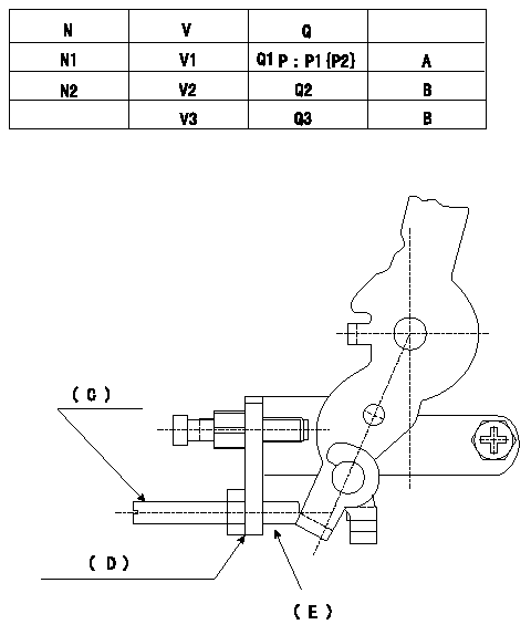
Adjusting method [applied voltage Vi, dummy bolt (C)]
1. Hold the dummy bolt (C) against the control lever at position N = N1, Q = Q1.
Fix using the lock nut.
2. When adjusting the potentiometer, position the control lever against the dummy bolt (C) and adjust the potentiometer so that the output voltage is V1 (V).
3. Remove the dummy bolt (C) after the completion of adjustment.
Confirm that the potentiometer output voltage is within the above mentioned standards between the control lever's adjusting point and the idling position.
N:Pump speed
V:Output voltage
Q:Injection quantity
P:Boost pressure
A:Adjusting point
B:Checking point
Q2:Idle
Q3:Full speed
(C): Dummy bolt
(D): Bracket for mounting the dummy bolt
(E): Part numbers of the dummy bolt and the nut
146526-3300 (bolt) 42L
013020-6040 (nut)
----------
N1=700r/min V1=3.06+-0.03V Q1=33.3+-1cm3/1,000st Vi=10V
----------
N1=700r/min N2=425r/min V1=3.06+-0.03V V2=1.02+-0.45V V3=-V Q1=33.3+-1cm3/1,000st Q2=10.5+-2cm3/1,000st(Idle) Q3=-cm3/1,000st P1=-kPa P2=-mmHg
----------
N1=700r/min V1=3.06+-0.03V Q1=33.3+-1cm3/1,000st Vi=10V
----------
N1=700r/min N2=425r/min V1=3.06+-0.03V V2=1.02+-0.45V V3=-V Q1=33.3+-1cm3/1,000st Q2=10.5+-2cm3/1,000st(Idle) Q3=-cm3/1,000st P1=-kPa P2=-mmHg
0000001901 V-FICD ADJUSTMENT
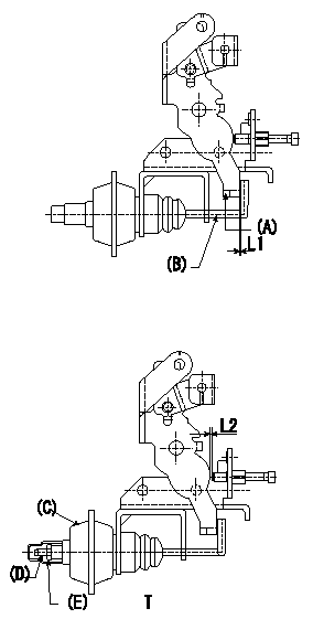
Checking the V-FICD
1. Adjust to obtain L1.
2. Apply P1{P2} negative pressure to the actuator. Confirm that the actuator shaft moves through its full stroke.
3. Apply negative pressure P1 (P2) to the actuator and move the V-FICD through its full stroke.
4. Adjust using the stroke adjusting screw so that the clearance between the control lever and the idling stopper bolt is L2.
(A) = control lever
(B) = actuator shaft
(C) = actuator
(D) = stroke adjusting screw
(E) = lock nut
----------
L=1+1mm L2=0.56+0.2mm P1=-53.3kPa P2=-400mmHg
----------
L1=1+1mm L2=0.56+0.2mm T=1.2~1.5Nm{0.12~0.15kgfm}
----------
L=1+1mm L2=0.56+0.2mm P1=-53.3kPa P2=-400mmHg
----------
L1=1+1mm L2=0.56+0.2mm T=1.2~1.5Nm{0.12~0.15kgfm}
0000002001 A/T PLATE ADJUSTMENT
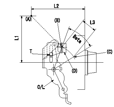
A/T plate adjustment
1. Turn the control lever from the idle position (B) to the Full speed position (C)
2. Adjust the A/T plate (D) so that (A)(C) - (A)(B) = L3, then fix.
----------
L3=33+-0.5mm
----------
L1=95.5mm L2=109.5mm L3=33+-0.5mm T=3.5~5N-m(0.35~0.5kgf-m)
----------
L3=33+-0.5mm
----------
L1=95.5mm L2=109.5mm L3=33+-0.5mm T=3.5~5N-m(0.35~0.5kgf-m)
0000002101 W-CSD ADJUSTMENT
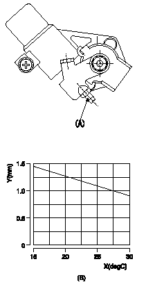
Adjustment of the W-CSD
Adjust the timer stroke
1. Adjust the timer stroke B so that it is as described in the graph below.
2. Adjust with the screw (A) so that the timer advance angle determined in item 1 is obtained.
(A) = screw
(B) = timer stroke : TA (mm) TA = -0.41t + 2.05
X = temperature t
Y = timer stroke: TA
----------
----------
----------
----------