Rating:
Information injection-pump assembly
ZEXEL
104740-1700
1047401700
ISUZU
8943260770
8943260770
Cross reference number
ZEXEL
104740-1700
1047401700
ISUZU
8943260770
8943260770
Zexel num
Bosch num
Firm num
Name
Calibration Data:
Adjustment conditions
Test oil
1404 Test oil ISO4113orSAEJ967d
1404 Test oil ISO4113orSAEJ967d
Test oil temperature
degC
45
45
50
Nozzle
105000-2010
Bosch type code
NP-DN12SD12TT
Nozzle holder
105780-2080
Opening pressure
MPa
14.7
14.7
15.19
Opening pressure
kgf/cm2
150
150
155
Injection pipe
Inside diameter - outside diameter - length (mm) mm 2-6-840
Inside diameter - outside diameter - length (mm) mm 2-6-840
Transfer pump pressure
kPa
20
20
20
Transfer pump pressure
kgf/cm2
0.2
0.2
0.2
Direction of rotation (viewed from drive side)
Right R
Right R
Injection timing adjustment
Pump speed
r/min
1250
1250
1250
Average injection quantity
mm3/st.
49.3
48.8
49.8
Difference in delivery
mm3/st.
3.5
Basic
*
Injection timing adjustment_02
Pump speed
r/min
2500
2500
2500
Average injection quantity
mm3/st.
14
10.5
17.5
Injection timing adjustment_03
Pump speed
r/min
2150
2150
2150
Average injection quantity
mm3/st.
40.7
38.2
43.2
Injection timing adjustment_04
Pump speed
r/min
1250
1250
1250
Average injection quantity
mm3/st.
49.3
48.3
50.3
Injection timing adjustment_05
Pump speed
r/min
600
600
600
Average injection quantity
mm3/st.
48.8
46.3
51.3
Injection quantity adjustment
Pump speed
r/min
2500
2500
2500
Average injection quantity
mm3/st.
14
11
17
Difference in delivery
mm3/st.
4.5
Basic
*
Injection quantity adjustment_02
Pump speed
r/min
2850
2850
2850
Average injection quantity
mm3/st.
5
Governor adjustment
Pump speed
r/min
425
425
425
Average injection quantity
mm3/st.
10.3
8.3
12.3
Difference in delivery
mm3/st.
2
Basic
*
Governor adjustment_02
Pump speed
r/min
425
425
425
Average injection quantity
mm3/st.
10.3
8.3
12.3
Governor adjustment_03
Pump speed
r/min
700
700
700
Average injection quantity
mm3/st.
3
Timer adjustment
Pump speed
r/min
100
100
100
Average injection quantity
mm3/st.
60
50
70
Basic
*
Speed control lever angle
Pump speed
r/min
425
425
425
Average injection quantity
mm3/st.
0
0
0
Remarks
Magnet OFF
Magnet OFF
0000000901
Pump speed
r/min
1250
1250
1250
Overflow quantity
cm3/min
420
288
552
Stop lever angle
Pump speed
r/min
1750
1750
1750
Pressure
kPa
588.5
569
608
Pressure
kgf/cm2
6
5.8
6.2
Basic
*
Stop lever angle_02
Pump speed
r/min
1750
1750
1750
Pressure
kPa
588.5
569
608
Pressure
kgf/cm2
6
5.8
6.2
Stop lever angle_03
Pump speed
r/min
2150
2150
2150
Pressure
kPa
666.5
637
696
Pressure
kgf/cm2
6.8
6.5
7.1
0000001101
Pump speed
r/min
1750
1750
1750
Timer stroke
mm
4.2
4
4.4
Basic
*
_02
Pump speed
r/min
1250
1250
1250
Timer stroke
mm
2
1.5
2.5
_03
Pump speed
r/min
1750
1750
1750
Timer stroke
mm
4.2
3.8
4.6
_04
Pump speed
r/min
2150
2150
2150
Timer stroke
mm
5.85
5.3
6.4
0000001201
Max. applied voltage
V
8
8
8
Test voltage
V
13
12
14
0000001401
Pump speed
r/min
1750
1750
1750
Average injection quantity
mm3/st.
34
33.5
34.5
Timer stroke variation dT
mm
0.8
0.6
1
Basic
*
_02
Pump speed
r/min
1750
1750
1750
Average injection quantity
mm3/st.
34
33
35
Timer stroke variation dT
mm
0.8
0.5
1.1
_03
Pump speed
r/min
1750
1750
1750
Average injection quantity
mm3/st.
25
23.5
26.5
Timer stroke variation dT
mm
1.6
1.1
2.1
Timing setting
K dimension
mm
3.3
3.2
3.4
KF dimension
mm
5.8
5.7
5.9
MS dimension
mm
0.9
0.8
1
Pre-stroke
mm
0.2
0.18
0.22
Control lever angle alpha
deg.
-2
-6
2
Control lever angle beta
deg.
38
33
43
Test data Ex:
0000001801 V-FICD ADJUSTMENT
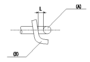
Adjustment of the V-FICD
1. Adjust the actuator rod to obtain L1.
2. Apply negative pressure P1 {P2} to the actuator and confirm that it moves through its full stroke.
(A) actuator shaft
(B) Control lever
----------
L=1+1mm P1=-53.3kPa P2=-400mmHg
----------
L=1+1mm
----------
L=1+1mm P1=-53.3kPa P2=-400mmHg
----------
L=1+1mm
0000001901 V-FICD ADJUSTMENT
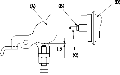
Adjustment of the V-FICD
Becomes L2 when negative pressure P3 {P4} applied to the actuator.
To adjust the stroke adjust the actuator's stroke adjusting screw (C).
(A) Control lever
(B): lock nut
(C): stroke adjusting screw
(D): Actuator
----------
L2=0.56+-0.2mm P3=-53.3kPa P4=-400mmHg
----------
S=-mm L2=0.56+-0.2mm T=1.2~1.5N-m{0.12~0.15kgf-m}
----------
L2=0.56+-0.2mm P3=-53.3kPa P4=-400mmHg
----------
S=-mm L2=0.56+-0.2mm T=1.2~1.5N-m{0.12~0.15kgf-m}
0000002001 A/T PLATE ADJUSTMENT
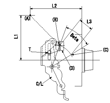
A/T plate adjustment
1. Turn the control lever from the idle position (B) to the Full speed position (C)
2. Adjust the A/T plate (D) so that (A)(C) - (A)(B) = L3, then fix.
----------
L3=33+-0.5mm
----------
L1=95.5mm L2=109.5mm L3=33+-0.5mm T=3.5~5N-m(0.35~0.5kgf-m)
----------
L3=33+-0.5mm
----------
L1=95.5mm L2=109.5mm L3=33+-0.5mm T=3.5~5N-m(0.35~0.5kgf-m)