Rating:
Information injection-pump assembly
ZEXEL
104701-2040
1047012040
Cross reference number
ZEXEL
104701-2040
1047012040
Zexel num
Bosch num
Firm num
Name
104701-2040
INJECTION-PUMP ASSEMBLY
Calibration Data:
Adjustment conditions
Test oil
1404 Test oil ISO4113orSAEJ967d
1404 Test oil ISO4113orSAEJ967d
Test oil temperature
degC
45
45
50
Nozzle
105780-0060
Bosch type code
NP-DN0SD1510
Nozzle holder
105780-2150
Opening pressure
MPa
13
13
13.3
Opening pressure
kgf/cm2
133
133
136
Injection pipe
157805-7320
Injection pipe
Inside diameter - outside diameter - length (mm) mm 2-6-450
Inside diameter - outside diameter - length (mm) mm 2-6-450
Joint assembly
157641-4720
Tube assembly
157641-4020
Transfer pump pressure
kPa
20
20
20
Transfer pump pressure
kgf/cm2
0.2
0.2
0.2
Direction of rotation (viewed from drive side)
Right R
Right R
Governor adjustment
Pump speed
r/min
1000
1000
1000
TCV duty (%) F TCV 60Hz
%
100
100
100
U alpha soll
V
2.7
2.7
2.7
Pump chamber pressure
kPa
617.5
588
647
Pump chamber pressure
kgf/cm2
6.3
6
6.6
Basic
*
Governor adjustment_02
Pump speed
r/min
100
100
100
TCV duty (%) F TCV 60Hz
%
100
100
100
U alpha soll
V
2.7
2.7
2.7
Pump chamber pressure
kPa
294
294
Pump chamber pressure
kgf/cm2
3
3
Governor adjustment_03
Pump speed
r/min
1000
1000
1000
TCV duty (%) F TCV 60Hz
%
100
100
100
U alpha soll
V
2.7
2.7
2.7
Pump chamber pressure
kPa
618
579
657
Pump chamber pressure
kgf/cm2
6.3
5.9
6.7
Governor adjustment_04
Pump speed
r/min
2000
2000
2000
TCV duty (%) F TCV 60Hz
%
100
100
100
U alpha soll
V
2.7
2.7
2.7
Pump chamber pressure
kPa
755
706
804
Pump chamber pressure
kgf/cm2
7.7
7.2
8.2
Boost compensator adjustment
Pump speed
r/min
1000
1000
1000
TCV duty (%) F TCV 60Hz
%
70
70
70
U alpha soll
V
2.7
2.7
2.7
Timer stroke
mm
4.1
3.9
4.3
Basic
*
Boost compensator adjustment_02
Pump speed
r/min
500
500
500
TCV duty (%) F TCV 60Hz
%
100
100
100
U alpha soll
V
2.7
2.7
2.7
Timer stroke
mm
7.4
5.4
9.4
Boost compensator adjustment_03
Pump speed
r/min
1000
1000
1000
TCV duty (%) F TCV 60Hz
%
100
100
100
U alpha soll
V
2.7
2.7
2.7
Timer stroke
mm
8.1
6.1
10.1
Boost compensator adjustment_04
Pump speed
r/min
1000
1000
1000
TCV duty (%) F TCV 60Hz
%
70
70
70
U alpha soll
V
2.7
2.7
2.7
Timer stroke
mm
4.1
3.8
4.4
Boost compensator adjustment_05
Pump speed
r/min
1000
1000
1000
TCV duty (%) F TCV 60Hz
%
0
0
0
U alpha soll
V
2.7
2.7
2.7
Timer stroke
mm
0
0
0
Boost compensator adjustment_06
Pump speed
r/min
1500
1500
1500
TCV duty (%) F TCV 60Hz
%
100
100
100
U alpha soll
V
2.7
2.7
2.7
Timer stroke
mm
9.75
9.3
10.2
Speed control lever angle
Pump speed
r/min
1000
1000
1000
TCV duty (%) F TCV 60Hz
%
100
100
100
U alpha soll
V
2.7
2.7
2.7
Overflow quantity
cm3/min
600
470
730
0000000901
Pump speed
r/min
1000
1000
1000
U alpha soll + dU alpha soll
V
2.8
2.8
2.8
TCV duty (%) F TCV 60Hz
%
100
100
100
Average injection quantity
mm3/st.
80.5
80
81
Difference in delivery
mm3/st.
5
Basic
*
_02
Pump speed
r/min
375
375
375
U alpha soll + dU alpha soll
V
1.89
1.89
1.89
TCV duty (%) F TCV 60Hz
%
100
100
100
Average injection quantity
mm3/st.
7
4
10
Difference in delivery
mm3/st.
2
Basic
*
Remarks
Confirmation of difference in delivery
Confirmation of difference in delivery
_03
Pump speed
r/min
2500
2500
2500
U alpha soll + dU alpha soll
V
1.66
1.66
1.66
TCV duty (%) F TCV 60Hz
%
100
100
100
Average injection quantity
mm3/st.
16.1
13.6
18.6
Difference in delivery
mm3/st.
5
Basic
*
Remarks
Confirmation of difference in delivery
Confirmation of difference in delivery
_04
Pump speed
r/min
100
100
100
U alpha soll + dU alpha soll
V
3.5
3.5
3.5
TCV duty (%) F TCV 60Hz
%
100
100
100
Average injection quantity
mm3/st.
83.3
73.3
93.3
_05
Pump speed
r/min
375
375
375
U alpha soll + dU alpha soll
V
1.89
1.89
1.89
TCV duty (%) F TCV 60Hz
%
100
100
100
Average injection quantity
mm3/st.
7
4
10
_06
Pump speed
r/min
500
500
500
U alpha soll + dU alpha soll
V
2.49
2.49
2.49
TCV duty (%) F TCV 60Hz
%
100
100
100
Average injection quantity
mm3/st.
50.1
48.1
52.1
_07
Pump speed
r/min
800
800
800
U alpha soll + dU alpha soll
V
1.86
1.86
1.86
TCV duty (%) F TCV 60Hz
%
100
100
100
Average injection quantity
mm3/st.
15.4
13.4
17.4
_08
Pump speed
r/min
800
800
800
U alpha soll + dU alpha soll
V
2.62
2.62
2.62
TCV duty (%) F TCV 60Hz
%
100
100
100
Average injection quantity
mm3/st.
64.4
62.4
66.4
_09
Pump speed
r/min
1000
1000
1000
U alpha soll + dU alpha soll
V
1.85
1.85
1.85
TCV duty (%) F TCV 60Hz
%
100
100
100
Average injection quantity
mm3/st.
16.6
14.6
18.6
_10
Pump speed
r/min
1000
1000
1000
U alpha soll + dU alpha soll
V
2.8
2.8
2.8
TCV duty (%) F TCV 60Hz
%
100
100
100
Average injection quantity
mm3/st.
80.5
79.5
81.5
_11
Pump speed
r/min
2000
2000
2000
U alpha soll + dU alpha soll
V
2.58
2.58
2.58
TCV duty (%) F TCV 60Hz
%
100
100
100
Average injection quantity
mm3/st.
63.7
61.7
65.7
_12
Pump speed
r/min
2250
2250
2250
U alpha soll + dU alpha soll
V
2.43
2.43
2.43
TCV duty (%) F TCV 60Hz
%
100
100
100
Average injection quantity
mm3/st.
54.3
51.8
56.8
_13
Pump speed
r/min
2500
2500
2500
U alpha soll + dU alpha soll
V
1.66
1.66
1.66
TCV duty (%) F TCV 60Hz
%
100
100
100
Average injection quantity
mm3/st.
16.1
13.6
18.6
_14
Pump speed
r/min
2500
2500
2500
U alpha soll + dU alpha soll
V
1
1
1
TCV duty (%) F TCV 60Hz
%
100
100
100
Average injection quantity
mm3/st.
3
Stop lever angle
Pump speed
r/min
375
375
375
U alpha soll + dU alpha soll
V
1.89
1.89
1.89
TCV duty (%) F TCV 60Hz
%
0
0
0
Average injection quantity
cm3/min
0
0
0
Stop lever angle_02
Pump speed
r/min
2250
2250
2250
U alpha soll + dU alpha soll
V
2.43
2.43
2.43
TCV duty (%) F TCV 60Hz
%
100
100
100
Average injection quantity
cm3/min
0
0
0
0000001101
Pump speed
r/min
200
200
200
TCV duty (%) F TCV 60Hz
%
100
100
100
U alpha soll
V
2.7
2.7
2.7
Speed output
N=Measure the actual speed. r/min N+-8
N=Measure the actual speed. r/min N+-8
0000001201
Pump speed
r/min
1000
1000
1000
TCV duty (%) F TCV 60Hz
%
100
100
100
U alpha soll
V
2.8
2.8
2.8
Temperature output
Measure T = actual output temperature degC T+-5
Measure T = actual output temperature degC T+-5
0000001301
Max. applied voltage
V
8
8
8
Test voltage
V
13
12
14
0000001401
K dimension
mm
3.3
3.2
3.4
KF dimension
mm
5.62
5.52
5.72
Pre-stroke
mm
0.1
0.08
0.12
Test data Ex:
Injection timing adjustment Comp. resistor/voltage
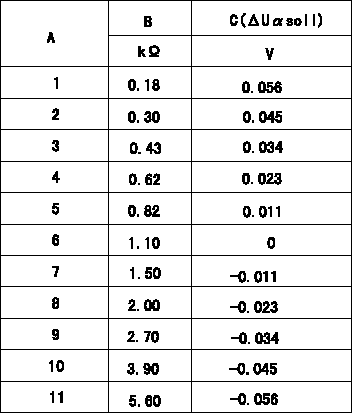
Compensation resistance/compensation voltage comparison
A = Compensation resistor number
B= Compensation resistance
C = Compensation voltage delta U alpha soll
----------
----------
----------
----------
0000001601 HARNESS & CONNECTOR
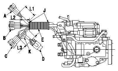
Corrugated tube assembly specification
(1)Maintain the corrugated tube so that the dimension of the end of the connector and the end of the corrugated are as shown in the figure.
(2)At K, pull the Q adjustment resistor towards the clip.
(3)Wrap black vinyl tape 4 times around the end of the corrugated tube to fix the tube.
A:RS03M-GY
B:RS08M-GY
C:RS08M-B
D:Q adjustment resistor
E:Corrugated tube
J:PVC tape
----------
----------
L1=50+-10mm L2=40+-10mm L3=50+-10mm
----------
----------
L1=50+-10mm L2=40+-10mm L3=50+-10mm
0000001701 HARNESS & CONNECTOR
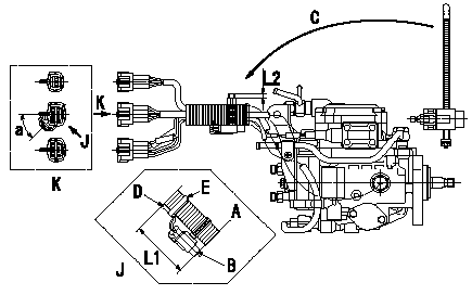
Injection quantity adjustment compensation resistor assembly standards
(1)Fix the injection quantity adjustment compensation resistor (Q adjustment resistor) using clips.
(2)After fixing the corrugated tube, and with the corrugated tube's end and the end of the Q adjustment resistor aligned, fix the Q adjustment resistor so that it is positioned in the direction shown by the arrow in the figure (each connector clip side a) .
(3)Fix the Q adjustment harness's protective tube to the corrugated tube using black PVC tape.
(4)After confirming that the Q adjustment resistor is fixed in the position as shown by the arrow in diagram K, cut off the excess clip to leave L2.
A:Align the end of the corrugated tube and the end of the Q adjustment resistor.
B:Injection quantity adjustment compensation resistor (Q adjustment resistor)
C:After attaching the clip to the Q adjustment resistor, fix the corrugated tube.
D:Q adjustment resistor harness protective tube
E:PVC tape
K:Figure shown by arrow
J:Figure shown by arrow
----------
----------
a=(45deg) L1=(90mm) L2=(5mm)
----------
----------
a=(45deg) L1=(90mm) L2=(5mm)
Have questions with 104701-2040?
Group cross 104701-2040 ZEXEL
104701-2040
INJECTION-PUMP ASSEMBLY