Rating:
Information injection-pump assembly
BOSCH
9 460 614 249
9460614249
ZEXEL
104700-9130
1047009130
Cross reference number
BOSCH
9 460 614 249
9460614249
ZEXEL
104700-9130
1047009130
Zexel num
Bosch num
Firm num
Name
104700-9130
9 460 614 249
INJECTION-PUMP ASSEMBLY
4D56TCI
4D56TCI
Calibration Data:
Adjustment conditions
Test oil
1404 Test oil ISO4113orSAEJ967d
1404 Test oil ISO4113orSAEJ967d
Test oil temperature
degC
45
45
50
Nozzle
105780-0060
Bosch type code
NP-DN0SD1510
Nozzle holder
105780-2150
Opening pressure
MPa
13
13
13.3
Opening pressure
kgf/cm2
133
133
136
Injection pipe
157805-7320
Injection pipe
Inside diameter - outside diameter - length (mm) mm 2-6-450
Inside diameter - outside diameter - length (mm) mm 2-6-450
Joint assembly
157641-4720
Tube assembly
157641-4020
Transfer pump pressure
kPa
20
20
20
Transfer pump pressure
kgf/cm2
0.2
0.2
0.2
Direction of rotation (viewed from drive side)
Right R
Right R
Governor adjustment
Pump speed
r/min
1000
1000
1000
TCV duty (%) F TCV 60Hz
%
100
100
100
U alpha soll
V
2.7
2.7
2.7
Pump chamber pressure
kPa
598.5
569
628
Pump chamber pressure
kgf/cm2
6.1
5.8
6.4
Basic
*
Governor adjustment_02
Pump speed
r/min
100
100
100
TCV duty (%) F TCV 60Hz
%
100
100
100
U alpha soll
V
2.7
2.7
2.7
Pump chamber pressure
kPa
294
294
Pump chamber pressure
kgf/cm2
3
3
Governor adjustment_03
Pump speed
r/min
1000
1000
1000
TCV duty (%) F TCV 60Hz
%
100
100
100
U alpha soll
V
2.7
2.7
2.7
Pump chamber pressure
kPa
598.5
559
638
Pump chamber pressure
kgf/cm2
6.1
5.7
6.5
Governor adjustment_04
Pump speed
r/min
2000
2000
2000
TCV duty (%) F TCV 60Hz
%
100
100
100
U alpha soll
V
2.7
2.7
2.7
Pump chamber pressure
kPa
736
687
785
Pump chamber pressure
kgf/cm2
7.5
7
8
Boost compensator adjustment
Pump speed
r/min
1000
1000
1000
TCV duty (%) F TCV 60Hz
%
100
100
100
U alpha soll
V
2.7
2.7
2.7
Timer stroke
mm
7.7
7.5
7.9
Basic
*
Boost compensator adjustment_02
Pump speed
r/min
100
100
100
TCV duty (%) F TCV 60Hz
%
100
100
100
U alpha soll
V
2.7
2.7
2.7
Timer stroke
mm
1.8
0.3
3.3
Boost compensator adjustment_03
Pump speed
r/min
350
350
350
TCV duty (%) F TCV 60Hz
%
100
100
100
U alpha soll
V
2.7
2.7
2.7
Timer stroke
mm
5.2
3.1
7.3
Boost compensator adjustment_04
Pump speed
r/min
1000
1000
1000
TCV duty (%) F TCV 60Hz
%
100
100
100
U alpha soll
V
2.7
2.7
2.7
Timer stroke
mm
7.7
7.4
8
Boost compensator adjustment_05
Pump speed
r/min
1000
1000
1000
TCV duty (%) F TCV 60Hz
%
70
70
70
U alpha soll
V
2.7
2.7
2.7
Timer stroke
mm
4
1.9
6.1
Boost compensator adjustment_06
Pump speed
r/min
2000
2000
2000
TCV duty (%) F TCV 60Hz
%
100
100
100
U alpha soll
V
2.7
2.7
2.7
Timer stroke
mm
9.75
9.3
10.2
Boost compensator adjustment_07
Pump speed
r/min
2000
2000
2000
TCV duty (%) F TCV 60Hz
%
0
0
0
U alpha soll
V
2.7
2.7
2.7
Timer stroke
mm
0
0
0
Timer adjustment
Pump speed
r/min
1000
1000
1000
TCV duty (%) F TCV 60Hz
%
0
0
0
U alpha soll
V
2.7
2.7
2.7
Vtps
V
0.51
0.382
0.638
Basic
*
Timer adjustment_02
Pump speed
r/min
1000
1000
1000
TCV duty (%) F TCV 60Hz
%
0
0
0
U alpha soll
V
2.7
2.7
2.7
Vtps
V
0.51
0.382
0.638
Timer adjustment_03
Pump speed
r/min
1000
1000
1000
TCV duty (%) F TCV 60Hz
%
100
100
100
U alpha soll
V
2.7
2.7
2.7
Vtps
V
1.925
1.702
2.148
Speed control lever angle
Pump speed
r/min
1000
1000
1000
TCV duty (%) F TCV 60Hz
%
100
100
100
U alpha soll
V
2.7
2.7
2.7
Overflow quantity
cm3/min
550
420
680
0000000901
Pump speed
r/min
1250
1250
1250
U alpha soll + dU alpha soll
V
2.9
2.9
2.9
TCV duty (%) F TCV 60Hz
%
100
100
100
Average injection quantity
mm3/st.
72.1
71.6
72.6
Difference in delivery
mm3/st.
3.5
Basic
*
_02
Pump speed
r/min
375
375
375
U alpha soll + dU alpha soll
V
1.9
1.9
1.9
TCV duty (%) F TCV 60Hz
%
100
100
100
Average injection quantity
mm3/st.
13.3
10.3
16.3
Difference in delivery
mm3/st.
2.5
Basic
*
Remarks
Confirmation of difference in delivery
Confirmation of difference in delivery
_03
Pump speed
r/min
2650
2650
2650
U alpha soll + dU alpha soll
V
1.8
1.8
1.8
TCV duty (%) F TCV 60Hz
%
100
100
100
Average injection quantity
mm3/st.
16.9
14.4
19.4
Difference in delivery
mm3/st.
5.5
Basic
*
Remarks
Confirmation of difference in delivery
Confirmation of difference in delivery
_04
Pump speed
r/min
100
100
100
U alpha soll + dU alpha soll
V
2.9
2.9
2.9
TCV duty (%) F TCV 60Hz
%
100
100
100
Average injection quantity
mm3/st.
51.9
41.9
61.9
_05
Pump speed
r/min
375
375
375
U alpha soll + dU alpha soll
V
1.9
1.9
1.9
TCV duty (%) F TCV 60Hz
%
100
100
100
Average injection quantity
mm3/st.
13.3
10.3
16.3
_06
Pump speed
r/min
500
500
500
U alpha soll + dU alpha soll
V
2.57
2.57
2.57
TCV duty (%) F TCV 60Hz
%
100
100
100
Average injection quantity
mm3/st.
50.8
48.3
53.3
_07
Pump speed
r/min
750
750
750
U alpha soll + dU alpha soll
V
2.79
2.79
2.79
TCV duty (%) F TCV 60Hz
%
100
100
100
Average injection quantity
mm3/st.
66.6
64.1
69.1
_08
Pump speed
r/min
1000
1000
1000
U alpha soll + dU alpha soll
V
2.88
2.88
2.88
TCV duty (%) F TCV 60Hz
%
100
100
100
Average injection quantity
mm3/st.
71.7
69.2
74.2
_09
Pump speed
r/min
1250
1250
1250
U alpha soll + dU alpha soll
V
2.9
2.9
2.9
TCV duty (%) F TCV 60Hz
%
100
100
100
Average injection quantity
mm3/st.
72.1
71.1
73.1
_10
Pump speed
r/min
1500
1500
1500
U alpha soll + dU alpha soll
V
2.86
2.86
2.86
TCV duty (%) F TCV 60Hz
%
100
100
100
Average injection quantity
mm3/st.
71.2
68.7
73.7
_11
Pump speed
r/min
1750
1750
1750
U alpha soll + dU alpha soll
V
2.88
2.88
2.88
TCV duty (%) F TCV 60Hz
%
100
100
100
Average injection quantity
mm3/st.
69.6
67.1
72.1
_12
Pump speed
r/min
2000
2000
2000
U alpha soll + dU alpha soll
V
2.84
2.84
2.84
TCV duty (%) F TCV 60Hz
%
100
100
100
Average injection quantity
mm3/st.
67.6
65.1
70.1
_13
Pump speed
r/min
2650
2650
2650
U alpha soll + dU alpha soll
V
1.8
1.8
1.8
TCV duty (%) F TCV 60Hz
%
100
100
100
Average injection quantity
mm3/st.
16.9
14.4
19.4
_14
Pump speed
r/min
2650
2650
2650
U alpha soll + dU alpha soll
V
1
1
1
TCV duty (%) F TCV 60Hz
%
100
100
100
Average injection quantity
mm3/st.
3
Stop lever angle
Pump speed
r/min
2000
2000
2000
U alpha soll + dU alpha soll
V
2.84
2.84
2.84
TCV duty (%) F TCV 60Hz
%
100
100
100
Average injection quantity
cm3/min
0
0
0
0000001101
Pump speed
r/min
200
200
200
TCV duty (%) F TCV 60Hz
%
100
100
100
U alpha soll
V
2.7
2.7
2.7
Speed output
N=Measure the actual speed. r/min N+-8
N=Measure the actual speed. r/min N+-8
0000001201
Pump speed
r/min
1250
1250
1250
TCV duty (%) F TCV 60Hz
%
100
100
100
U alpha soll
V
2.9
2.9
2.9
Temperature output
Measure T = actual output temperature degC T+-5
Measure T = actual output temperature degC T+-5
0000001301
Max. applied voltage
V
8
8
8
Test voltage
V
13
12
14
0000001401
K dimension
mm
3.3
3.2
3.4
KF dimension
mm
5.9
5.8
6
Pre-stroke
mm
0.1
0.08
0.12
Test data Ex:
Injection timing adjustment Comp. resistor/voltage
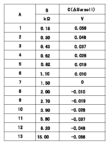
Compensation resistance/compensation voltage comparison
A = Compensation resistor number
B= Compensation resistance
C = Compensation voltage delta U alpha soll
----------
----------
----------
----------
0000001601 HARNESS & CONNECTOR
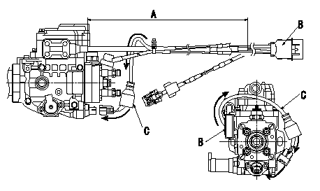
T.C.V. connector assembly specification
(1)Ensure the GE cable is not twisted at section A.
(2)Refer to diagram for direction of connector B.
(3)Route the TCV harnes C in the direction indicated by the arrows in the figure and install the connector.
----------
----------
----------
----------
0000001701 HARNESS & CONNECTOR
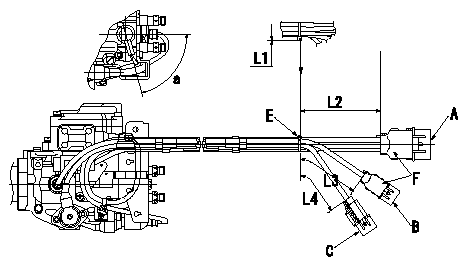
Harness position specification
(1)Install the rear cover of the GE side connector and the NP and FCV connector.
(2)Fix the harness using clips to the dimensions shown in the figure.
(3)Cut A to L1 or less.
(4)After completing the procedures, the lead wires must not be exposed or visible at the connector's rear cover.
B = GE, TCV, Q adjustment
C=NP,FCV
D=TPS
E = binder
F = connector's rear cover
----------
----------
a=(75deg) L1=Max.2mm L2=85+11-9mm L3=65+11-9mm L4=55+11-9mm
----------
----------
a=(75deg) L1=Max.2mm L2=85+11-9mm L3=65+11-9mm L4=55+11-9mm
0000001801 HARNESS & CONNECTOR
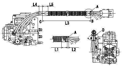
Corrugated tube assembly specification
(1)Align the end of the corrugated tube with clip A and fix it using black vinyl tape (L1, L2).
(2)Confirm that the dimension to the end of the corrugated tube C is L3, and fix it using black vinyl tape (L4, L5).
(3)Refer to the illustration for the position of the corrugated tube slit.
(4)After completing all of the procedures, ensure no lead wires are exposed after routing the harness.
A = binder
B = outside edge of binder
C = end of corrugated tube
D = position of corrugated tube's slit
----------
----------
L1=Max.25mm L2=Max.10mm L3=325+-10mm L4=(20mm) L5=(30mm) a=45deg
----------
----------
L1=Max.25mm L2=Max.10mm L3=325+-10mm L4=(20mm) L5=(30mm) a=45deg
0000001901 HARNESS & CONNECTOR
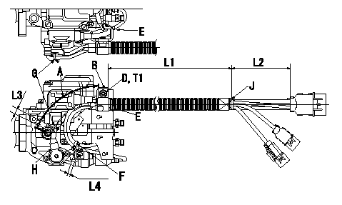
Harness fixing specification
(1)At the clip position J at dimension L2 from the rear end of the connector, and the dimension L1 from the metal end of the clip B, fix using the socket head bolt and the spring washer.
(2)Adjust the length of dimension L1 within the tolerance so that the TPS and Np harness at A is not excessively loose, then fix using the clip.
(3)Clip the GE cable and the FCV harness using clip E, the GE cable and the FCV-TCV harness using clip F, and the TPS-NP harness using clip G.
(4)Attach the binder G after ensuring that the TPS cover H is not loose.
B = clip
D = socket head bolt
E = binder
F = binder
G=Binder
H = TPS cover
J = clip position
----------
----------
L1=300+-10mm L2=(85mm) L3=5~15mm L4=5~15mm T1=9.8~13.7N-m(1.0~1.4kgf-m)
----------
----------
L1=300+-10mm L2=(85mm) L3=5~15mm L4=5~15mm T1=9.8~13.7N-m(1.0~1.4kgf-m)
0000002001 HARNESS & CONNECTOR
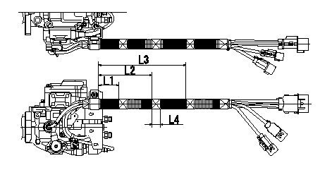
Vinyl tape assembly specification
Wrap with black vinyl tape (at 3 positions) from the end of the clip's metal portion at the positions shown in the figure (dimensions indicated).
----------
----------
L1=55+-10mm L2=125+-10mm L3=195+-10mm L4=(20mm)
----------
----------
L1=55+-10mm L2=125+-10mm L3=195+-10mm L4=(20mm)
0000002101 HARNESS & CONNECTOR
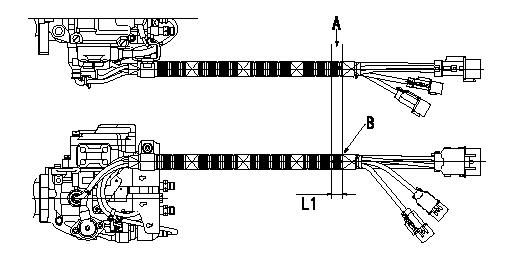
Marking application specification
(1)Ensure the corrugated tube is not twisted and then mark the position A shown in the figure.
(2)2) Use indelible paint for steel.
(3)3) Mark at the two locations indicated in the figure ( viewed from the side of the pump and the top of the pump). The markings must be the dimensions shown and approx. 5 mm wide.
A = white marking
B = End of tape binding
----------
----------
L1=20+-5mm
----------
----------
L1=20+-5mm
Have questions with 104700-9130?
Group cross 104700-9130 ZEXEL
Hyundai
Hyundai
Hyundai
Hyundai
104700-9130
9 460 614 249
INJECTION-PUMP ASSEMBLY
4D56TCI
4D56TCI