
Rating:
Information injection-pump assembly
BOSCH
9 400 616 362
9400616362
ZEXEL
103682-0420
1036820420
KOMATSU
6162731652
6162731652
Service parts 103682-0420 INJECTION-PUMP ASSEMBLY:
1.
_
5.
AUTOM. ADVANCE MECHANIS
7.
COUPLING PLATE
8.
_
9.
_
11.
Nozzle and Holder
6164-11-3101
12.
Open Pre:MPa(Kqf/cm2)
29.4{300}
15.
NOZZLE SET
Cross reference number
BOSCH
9 400 616 362
9400616362
ZEXEL
103682-0420
1036820420
KOMATSU
6162731652
6162731652
Zexel num
Bosch num
Firm num
Name
Calibration Data:
Adjustment conditions
Test oil
1404 Test oil ISO4113 or {SAEJ967d}
1404 Test oil ISO4113 or {SAEJ967d}
Test oil temperature
degC
40
40
45
Nozzle and nozzle holder
105780-8130
Bosch type code
EFEP215A
Nozzle
105780-0050
Bosch type code
DN6TD119NP1T
Nozzle holder
105780-2090
Bosch type code
EFEP215
Opening pressure
MPa
17.2
Opening pressure
kgf/cm2
175
Injection pipe
Outer diameter - inner diameter - length (mm) mm 8-4-1500
Outer diameter - inner diameter - length (mm) mm 8-4-1500
Overflow valve (drive side)
131425-1620
Overflow valve opening pressure (drive side)
kPa
255
221
289
Overflow valve opening pressure (drive side)
kgf/cm2
2.6
2.25
2.95
Overflow valve (governor side)
131425-1620
Overflow valve opening pressure (governor side)
kPa
255
221
289
Overflow valve opening pressure (governor side)
kgf/cm2
2.6
2.25
2.95
Tester oil delivery pressure
kPa
157
157
157
Tester oil delivery pressure
kgf/cm2
1.6
1.6
1.6
Direction of rotation (viewed from drive side)
Left L
Left L
Injection timing adjustment
Direction of rotation (viewed from drive side)
Left L
Left L
Injection order
1-5-3-6-
2-4
Pre-stroke
mm
4.5
4.45
4.55
Beginning of injection position
Drive side NO.1
Drive side NO.1
Difference between angles 1
Cal 1-5 deg. 60 59.5 60.5
Cal 1-5 deg. 60 59.5 60.5
Difference between angles 2
Cal 1-3 deg. 120 119.5 120.5
Cal 1-3 deg. 120 119.5 120.5
Difference between angles 3
Cal 1-6 deg. 180 179.5 180.5
Cal 1-6 deg. 180 179.5 180.5
Difference between angles 4
Cyl.1-2 deg. 240 239.5 240.5
Cyl.1-2 deg. 240 239.5 240.5
Difference between angles 5
Cal 1-4 deg. 300 299.5 300.5
Cal 1-4 deg. 300 299.5 300.5
Injection quantity adjustment
Adjusting point
A
Rack position
15.5
Pump speed
r/min
1000
1000
1000
Average injection quantity
mm3/st.
535
530
540
Max. variation between cylinders
%
0
-4
4
Basic
*
Fixing the lever
*
Injection quantity adjustment_02
Adjusting point
B
Rack position
8.1+-0.5
Pump speed
r/min
300
300
300
Average injection quantity
mm3/st.
58
53
63
Max. variation between cylinders
%
0
-14
14
Fixing the rack
*
Injection quantity adjustment_03
Adjusting point
C
Rack position
16+0.2
Pump speed
r/min
100
100
100
Average injection quantity
mm3/st.
390
390
430
Fixing the lever
*
Rack limit
*
Test data Ex:
Governor adjustment
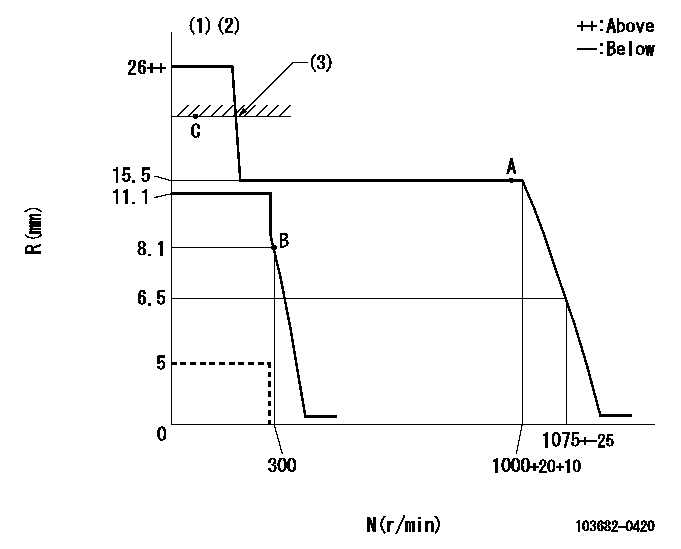
N:Pump speed
R:Rack position (mm)
(1)Target notch: K
(2)Deliver without the torque control spring operating.
(3)RACK LIMIT: RAL
----------
K=9 RAL=16+0.2mm
----------
----------
K=9 RAL=16+0.2mm
----------
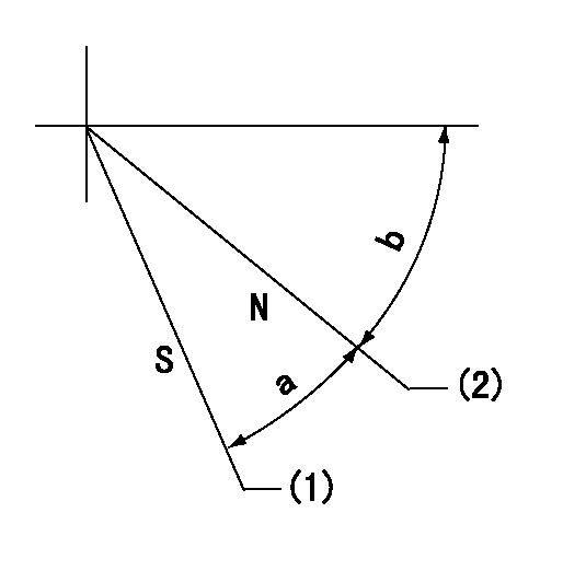
Speed control lever angle
F:Full speed
I:Idle
S:Stop
----------
----------
a=(16deg)+-5deg b=(42deg)+-5deg c=30deg+-3deg
----------
----------
a=(16deg)+-5deg b=(42deg)+-5deg c=30deg+-3deg
Stop lever angle
N:Pump normal
S:Stop the pump.
(1)Set the stopper bolt at speed = aa and rack position = bb.
(2)Clearance between stopper bolt and lever must be cc.
----------
aa=100r/min bb=5mm cc=(0.8)mm
----------
a=40deg+-5deg b=24deg+-5deg
----------
aa=100r/min bb=5mm cc=(0.8)mm
----------
a=40deg+-5deg b=24deg+-5deg
0000001501 Q ADJUSTMENT PIPING
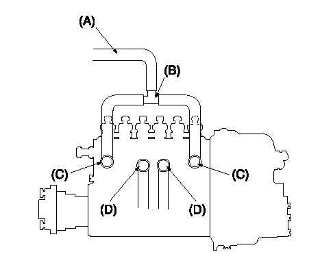
Tester fuel pipe A
(B) branch piping
Fuel inlet C
(D) Overflow valve
Piping at standard injection quantity adjustment
1. Because the pump gallery is divided into two, be careful of the fuel piping at adjustment.
----------
----------
----------
----------
Timing setting

(1)Pump vertical direction
(2)Coupling's key groove position at No 1 cylinder's beginning of injection
(3)-
(4)-
----------
----------
a=(70deg)
----------
----------
a=(70deg)