
Rating:
Information injection-pump assembly
BOSCH
9 400 616 176
9400616176
ZEXEL
101697-9110
1016979110
NISSAN-DIESEL
16714Z5614
16714z5614
Service parts 101697-9110 INJECTION-PUMP ASSEMBLY:
1.
_
7.
COUPLING PLATE
8.
_
9.
_
11.
Nozzle and Holder
16600-Z5570
12.
Open Pre:MPa(Kqf/cm2)
21.6{220}
15.
NOZZLE SET
Cross reference number
BOSCH
9 400 616 176
9400616176
ZEXEL
101697-9110
1016979110
NISSAN-DIESEL
16714Z5614
16714z5614
Zexel num
Bosch num
Firm num
Name
101697-9110
9 400 616 176
16714Z5614 NISSAN-DIESEL
INJECTION-PUMP ASSEMBLY
FE6T K 14BE INJECTION PUMP ASSY PE6A PE
FE6T K 14BE INJECTION PUMP ASSY PE6A PE
Calibration Data:
Adjustment conditions
Test oil
1404 Test oil ISO4113 or {SAEJ967d}
1404 Test oil ISO4113 or {SAEJ967d}
Test oil temperature
degC
40
40
45
Nozzle and nozzle holder
105780-8140
Bosch type code
EF8511/9A
Nozzle
105780-0000
Bosch type code
DN12SD12T
Nozzle holder
105780-2080
Bosch type code
EF8511/9
Opening pressure
MPa
17.2
Opening pressure
kgf/cm2
175
Injection pipe
Outer diameter - inner diameter - length (mm) mm 6-2-600
Outer diameter - inner diameter - length (mm) mm 6-2-600
Overflow valve
131424-1520
Overflow valve opening pressure
kPa
157
157
157
Overflow valve opening pressure
kgf/cm2
1.6
1.6
1.6
Tester oil delivery pressure
kPa
157
157
157
Tester oil delivery pressure
kgf/cm2
1.6
1.6
1.6
Direction of rotation (viewed from drive side)
Right R
Right R
Injection timing adjustment
Direction of rotation (viewed from drive side)
Right R
Right R
Injection order
1-4-2-6-
3-5
Pre-stroke
mm
3.4
3.35
3.45
Beginning of injection position
Drive side NO.1
Drive side NO.1
Difference between angles 1
Cal 1-4 deg. 60 59.5 60.5
Cal 1-4 deg. 60 59.5 60.5
Difference between angles 2
Cyl.1-2 deg. 120 119.5 120.5
Cyl.1-2 deg. 120 119.5 120.5
Difference between angles 3
Cal 1-6 deg. 180 179.5 180.5
Cal 1-6 deg. 180 179.5 180.5
Difference between angles 4
Cal 1-3 deg. 240 239.5 240.5
Cal 1-3 deg. 240 239.5 240.5
Difference between angles 5
Cal 1-5 deg. 300 299.5 300.5
Cal 1-5 deg. 300 299.5 300.5
Injection quantity adjustment
Adjusting point
-
Rack position
12.5
Pump speed
r/min
1500
1500
1500
Average injection quantity
mm3/st.
83.7
82.1
85.3
Max. variation between cylinders
%
0
-3.5
3.5
Basic
*
Fixing the rack
*
Standard for adjustment of the maximum variation between cylinders
*
Injection quantity adjustment_02
Adjusting point
H
Rack position
9.5+-0.5
Pump speed
r/min
300
300
300
Average injection quantity
mm3/st.
9.5
7.7
11.3
Max. variation between cylinders
%
0
-10
10
Fixing the rack
*
Standard for adjustment of the maximum variation between cylinders
*
Injection quantity adjustment_03
Adjusting point
A
Rack position
R1(12.5)
Pump speed
r/min
1500
1500
1500
Average injection quantity
mm3/st.
83.7
82.7
84.7
Basic
*
Fixing the lever
*
Injection quantity adjustment_04
Adjusting point
B
Rack position
R1-0.55
Pump speed
r/min
900
900
900
Average injection quantity
mm3/st.
68.7
66.7
70.7
Fixing the lever
*
Injection quantity adjustment_05
Adjusting point
I
Rack position
-
Pump speed
r/min
150
150
150
Average injection quantity
mm3/st.
85
85
105
Fixing the lever
*
Rack limit
*
Timer adjustment
Pump speed
r/min
1080--
Advance angle
deg.
0
0
0
Remarks
Start
Start
Timer adjustment_02
Pump speed
r/min
1030
Advance angle
deg.
0.5
Timer adjustment_03
Pump speed
r/min
1530
Advance angle
deg.
2
1.5
2.5
Remarks
Finish
Finish
Test data Ex:
Governor adjustment
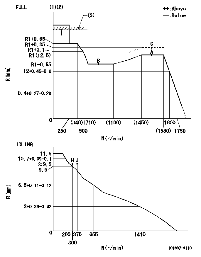
N:Pump speed
R:Rack position (mm)
(1)Torque cam stamping: T1
(2)Tolerance for racks not indicated: +-0.05mm.
(3)RACK LIMIT
----------
T1=N95
----------
----------
T1=N95
----------
Speed control lever angle
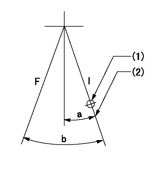
F:Full speed
I:Idle
(1)Use the hole at R = aa
(2)Stopper bolt setting
----------
aa=100mm
----------
a=26.5deg+-5deg b=(38deg)+-3deg
----------
aa=100mm
----------
a=26.5deg+-5deg b=(38deg)+-3deg
Stop lever angle

N:Pump normal
S:Stop the pump.
----------
----------
a=27deg+-5deg b=40deg+-5deg
----------
----------
a=27deg+-5deg b=40deg+-5deg
0000001501 TAMPER PROOF
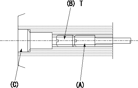
1. Method for setting tamperproof proofing
(1)Perform after governor adjustment (torque cam phase adjustment).
(2)Increase the full rack position to aa using the load lever.
(3)At N = N1, push in screw (A) until Ra.
(4)Temporarily caulk using the tip of a screwdriver
(5)Confirm that the rack at that time is Rb.
(6)Lock using setscrew (B). (Tightening torque = T)
(7)Pressfit (C) after applying adhesive.
(8)Readjust the full rack using the load lever.
----------
N1=1500r/min aa=(1)mm Ra=R1(12.5)+0.35mm Rb=R1(12.5)+0.35mm
----------
T=4.9~7N-m(0.5~0.7Kgf-m)
----------
N1=1500r/min aa=(1)mm Ra=R1(12.5)+0.35mm Rb=R1(12.5)+0.35mm
----------
T=4.9~7N-m(0.5~0.7Kgf-m)
Timing setting
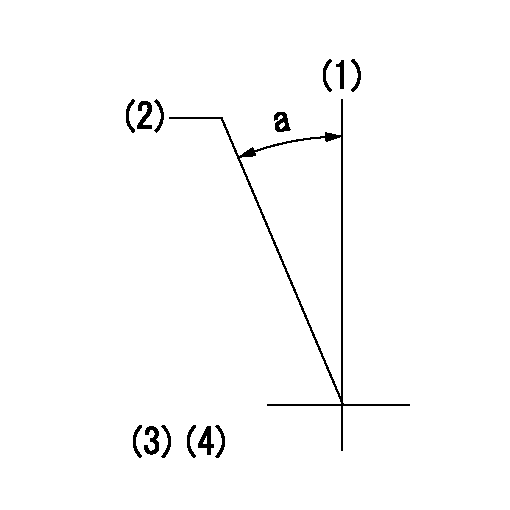
(1)Pump vertical direction
(2)Coupling's key groove position at No 1 cylinder's beginning of injection
(3)-
(4)-
----------
----------
a=(30deg)
----------
----------
a=(30deg)
Have questions with 101697-9110?
Group cross 101697-9110 ZEXEL
Nissan-Diesel
101697-9110
9 400 616 176
16714Z5614
INJECTION-PUMP ASSEMBLY
FE6T
FE6T