Rating:
Information injection-pump assembly
BOSCH
9 400 610 280
9400610280
ZEXEL
101631-9813
1016319813
NISSAN-DIESEL
16700C8607
16700c8607
Service parts 101631-9813 INJECTION-PUMP ASSEMBLY:
1.
_
6.
COUPLING PLATE
7.
COUPLING PLATE
8.
_
9.
_
11.
Nozzle and Holder
16600-36W00
12.
Open Pre:MPa(Kqf/cm2)
9.8{100}

15.
NOZZLE SET
Include in #1:
101631-9813
as INJECTION-PUMP ASSEMBLY
Include in #2:
104740-3420
as _
Cross reference number
BOSCH
9 400 610 280
9400610280
ZEXEL
101631-9813
1016319813
NISSAN-DIESEL
16700C8607
16700c8607
Zexel num
Bosch num
Firm num
Name
101631-9813
9 400 610 280
16700C8607 NISSAN-DIESEL
INJECTION-PUMP ASSEMBLY
SD33 * K
SD33 * K
Calibration Data:
Adjustment conditions
Test oil
1404 Test oil ISO4113 or {SAEJ967d}
1404 Test oil ISO4113 or {SAEJ967d}
Test oil temperature
degC
40
40
45
Nozzle and nozzle holder
105780-8140
Bosch type code
EF8511/9A
Nozzle
105780-0000
Bosch type code
DN12SD12T
Nozzle holder
105780-2080
Bosch type code
EF8511/9
Opening pressure
MPa
17.2
Opening pressure
kgf/cm2
175
Injection pipe
Outer diameter - inner diameter - length (mm) mm 6-2-600
Outer diameter - inner diameter - length (mm) mm 6-2-600
Tester oil delivery pressure
kPa
157
157
157
Tester oil delivery pressure
kgf/cm2
1.6
1.6
1.6
Direction of rotation (viewed from drive side)
Right R
Right R
Injection timing adjustment
Direction of rotation (viewed from drive side)
Right R
Right R
Injection order
1-4-2-6-
3-5
Pre-stroke
mm
2.15
2.1
2.2
Rack position
R=11.6
Beginning of injection position
Drive side NO.1
Drive side NO.1
Difference between angles 1
Cal 1-4 deg. 60 59.5 60.5
Cal 1-4 deg. 60 59.5 60.5
Difference between angles 2
Cyl.1-2 deg. 120 119.5 120.5
Cyl.1-2 deg. 120 119.5 120.5
Difference between angles 3
Cal 1-6 deg. 180 179.5 180.5
Cal 1-6 deg. 180 179.5 180.5
Difference between angles 4
Cal 1-3 deg. 240 239.5 240.5
Cal 1-3 deg. 240 239.5 240.5
Difference between angles 5
Cal 1-5 deg. 300 299.5 300.5
Cal 1-5 deg. 300 299.5 300.5
Injection quantity adjustment
Adjusting point
-
Rack position
11.6
Pump speed
r/min
800
800
800
Average injection quantity
mm3/st.
33.1
32.1
34.1
Max. variation between cylinders
%
0
-2.5
2.5
Basic
*
Fixing the rack
*
Injection quantity adjustment_02
Adjusting point
-
Rack position
8.1+-0.5
Pump speed
r/min
300
300
300
Average injection quantity
mm3/st.
7.5
6.4
8.6
Max. variation between cylinders
%
0
-15
15
Fixing the rack
*
Timer adjustment
Pump speed
r/min
550--
Advance angle
deg.
0
0
0
Remarks
Start
Start
Timer adjustment_02
Pump speed
r/min
500
Advance angle
deg.
0.5
Timer adjustment_03
Pump speed
r/min
1100
Advance angle
deg.
2.2
1.7
2.7
Timer adjustment_04
Pump speed
r/min
1900
Advance angle
deg.
7.5
7
8
Remarks
Finish
Finish
Test data Ex:
Governor adjustment
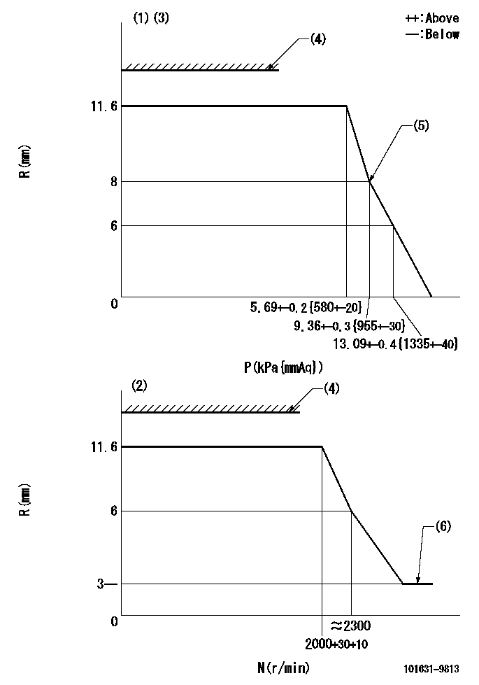
N:Pump speed
R:Rack position (mm)
P:Negative pressure
(1)Pneumatic governor
(2)Mechanical governor
(3)Acting negative pressure: P1
(4)RACK LIMIT: RAL
(5)Beginning of idle sub spring operation: L1
(6)Injection quantity Q = Q1 or less
----------
P1=3.63+-0.2kPa(370+-20mmAq) RAL=16-0.3mm L1=8+0.3mm Q1=3mm3/st
----------
----------
P1=3.63+-0.2kPa(370+-20mmAq) RAL=16-0.3mm L1=8+0.3mm Q1=3mm3/st
----------
Speed control lever angle
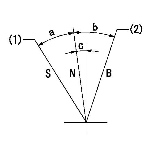
B:When boosted
N:Normal
S:Stop
(1)Rack position = aa
(2)Rack position bb
----------
aa=0mm bb=16mm
----------
a=23.5deg+-3deg b=8.5deg+-5deg c=2deg+-5deg
----------
aa=0mm bb=16mm
----------
a=23.5deg+-3deg b=8.5deg+-5deg c=2deg+-5deg
0000001501 ACS
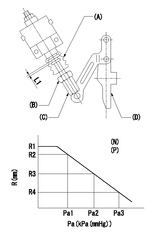
(N): Speed of the pump
(P): governor's negative pressure
(Pa): aneroid compensator's negative pressure
(A) rubber boot
(B) Nut
(c) Nut
(D) Lever
1. Aneroid compensator installation
(1)Turn nut (C) to adjust gap to L1. (Remove rubber boot at adjustment.)
(2)Lock using nut (B).
(3)After installation, the lever D must move smoothly when the lever D is moved to the excess fuel side, and R = R1 or more.
----------
L1=0.1~0.5mm R1=16mm
----------
N=1000r/min P=1.96kPa(200mmAq) R1=11.6mm R2=11.55mm R3=11+-0.2mm R4=10.8+-0.2mm Pa1=9.3-5.3kPa(70-40mmHg) Pa2=18kPa(135mmHg) Pa3=21.9kPa(164mmHg)
----------
L1=0.1~0.5mm R1=16mm
----------
N=1000r/min P=1.96kPa(200mmAq) R1=11.6mm R2=11.55mm R3=11+-0.2mm R4=10.8+-0.2mm Pa1=9.3-5.3kPa(70-40mmHg) Pa2=18kPa(135mmHg) Pa3=21.9kPa(164mmHg)
Timing setting
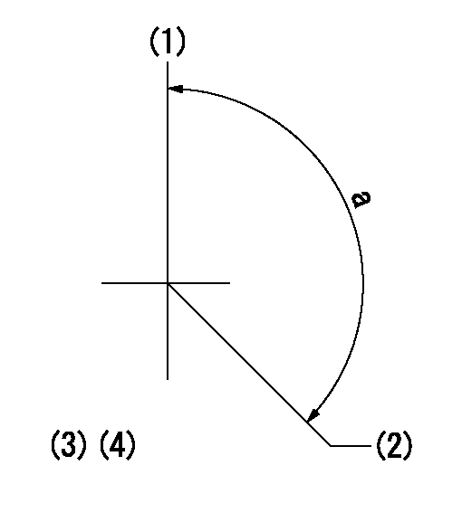
(1)Pump vertical direction
(2)Position of gear mark 'Y' at No 1 cylinder's beginning of injection
(3)B.T.D.C.: aa
(4)-
----------
aa=20deg
----------
a=(130deg)
----------
aa=20deg
----------
a=(130deg)
Have questions with 101631-9813?
Group cross 101631-9813 ZEXEL
Nissan-Diesel
101631-9813
9 400 610 280
16700C8607
INJECTION-PUMP ASSEMBLY
SD33
SD33