Rating:
Information injection-pump assembly
BOSCH
9 400 612 951
9400612951
ZEXEL
101609-9200
1016099200
MITSUBISHI-HEAV
3436501020
3436501020
Service parts 101609-9200 INJECTION-PUMP ASSEMBLY:
1.
_

5.
AUTOM. ADVANCE MECHANIS
6.
COUPLING PLATE
8.
_
9.
_
11.
Nozzle and Holder
12.
Open Pre:MPa(Kqf/cm2)
21.6{220}

15.
NOZZLE SET
Include in #1:
101609-9200
as INJECTION-PUMP ASSEMBLY
Include in #2:
104232-6010
as _
Cross reference number
BOSCH
9 400 612 951
9400612951
ZEXEL
101609-9200
1016099200
MITSUBISHI-HEAV
3436501020
3436501020
Zexel num
Bosch num
Firm num
Name
Calibration Data:
Adjustment conditions
Test oil
1404 Test oil ISO4113 or {SAEJ967d}
1404 Test oil ISO4113 or {SAEJ967d}
Test oil temperature
degC
40
40
45
Nozzle and nozzle holder
105780-8140
Bosch type code
EF8511/9A
Nozzle
105780-0000
Bosch type code
DN12SD12T
Nozzle holder
105780-2080
Bosch type code
EF8511/9
Opening pressure
MPa
17.2
Opening pressure
kgf/cm2
175
Injection pipe
Outer diameter - inner diameter - length (mm) mm 6-2-600
Outer diameter - inner diameter - length (mm) mm 6-2-600
Overflow valve
131424-5720
Overflow valve opening pressure
kPa
255
221
289
Overflow valve opening pressure
kgf/cm2
2.6
2.25
2.95
Tester oil delivery pressure
kPa
255
255
255
Tester oil delivery pressure
kgf/cm2
2.6
2.6
2.6
Direction of rotation (viewed from drive side)
Right R
Right R
Injection timing adjustment
Direction of rotation (viewed from drive side)
Right R
Right R
Injection order
1-5-3-6-
2-4
Pre-stroke
mm
3.5
3.45
3.55
Rack position
After adjusting injection quantity. R=A
After adjusting injection quantity. R=A
Beginning of injection position
Drive side NO.1
Drive side NO.1
Difference between angles 1
Cal 1-5 deg. 60 59.5 60.5
Cal 1-5 deg. 60 59.5 60.5
Difference between angles 2
Cal 1-3 deg. 120 119.5 120.5
Cal 1-3 deg. 120 119.5 120.5
Difference between angles 3
Cal 1-6 deg. 180 179.5 180.5
Cal 1-6 deg. 180 179.5 180.5
Difference between angles 4
Cyl.1-2 deg. 240 239.5 240.5
Cyl.1-2 deg. 240 239.5 240.5
Difference between angles 5
Cal 1-4 deg. 300 299.5 300.5
Cal 1-4 deg. 300 299.5 300.5
Injection quantity adjustment
Adjusting point
A
Rack position
9
Pump speed
r/min
895
895
895
Average injection quantity
mm3/st.
102.5
101.5
103.5
Max. variation between cylinders
%
0
-2.5
2.5
Basic
*
Fixing the lever
*
Injection quantity adjustment_02
Adjusting point
C
Rack position
5.8+-0.5
Pump speed
r/min
450
450
450
Average injection quantity
mm3/st.
13
11.7
14.3
Max. variation between cylinders
%
0
-14
14
Fixing the rack
*
Injection quantity adjustment_03
Adjusting point
D
Rack position
9.2++
Pump speed
r/min
100
100
100
Average injection quantity
mm3/st.
105
105
110
Fixing the lever
*
Rack limit
*
Test data Ex:
Governor adjustment
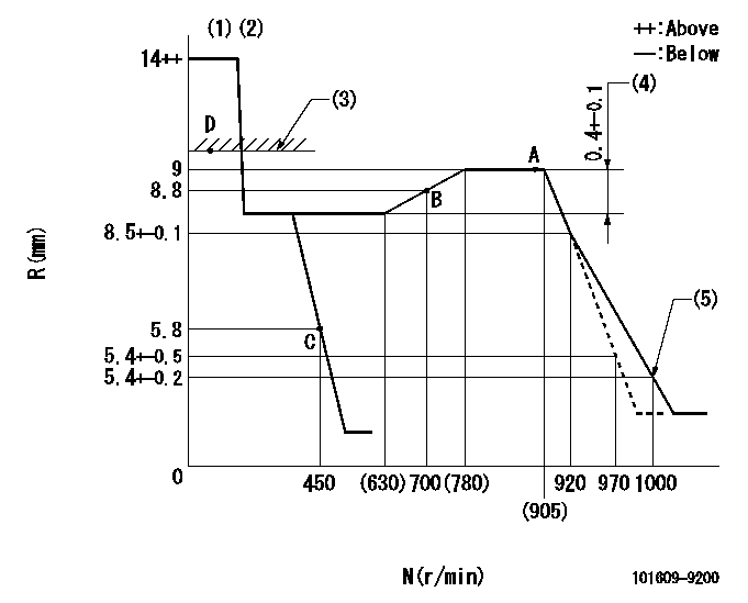
N:Pump speed
R:Rack position (mm)
(1)Target notch: K
(2)Tolerance for racks not indicated: +-0.05mm.
(3)RACK LIMIT
(4)Rack difference between N = N1 and N = N2
(5)Set idle sub-spring
----------
K=5 N1=895r/min N2=400r/min
----------
----------
K=5 N1=895r/min N2=400r/min
----------
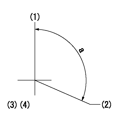
Speed control lever angle
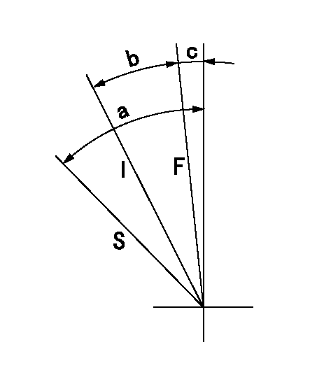
F:Full speed
I:Idle
S:Stop
----------
----------
a=31deg+-3deg b=12.5deg+-5deg c=5.5deg+-5deg
----------
----------
a=31deg+-3deg b=12.5deg+-5deg c=5.5deg+-5deg
Stop lever angle
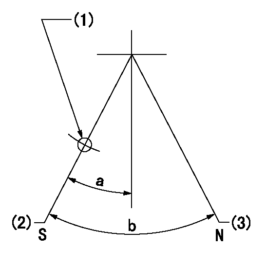
N:Pump normal
S:Stop the pump.
(1)Use the hole at R = aa
(2)Speed = bb, rack position = cc (sealed at delivery)
(3)Normal
----------
aa=25mm bb=0r/min cc=1-0.5mm
----------
a=21deg+-5deg b=(55deg)
----------
aa=25mm bb=0r/min cc=1-0.5mm
----------
a=21deg+-5deg b=(55deg)
0000001501 I/P WITH LOAD PLUNGER ADJ
Load plunger-equipped pump adjustment
1. Adjust the variation between cylinders and the injection quantity.
2. At Full point A, adjust the pre-stroke to the specified value.
3. After pre-stroke adjustment, reconfirm that the fuel injection quantity and the variation between cylinders is as specified.
----------
----------
----------
----------
Timing setting
(1)Pump vertical direction
(2)Position of gear mark '3' at No 1 cylinder's beginning of injection
(3)B.T.D.C.: aa
(4)After adjusting the injection quantity, adjust at rack position bb.
----------
aa=4deg bb=9mm
----------
a=(110deg)
----------
aa=4deg bb=9mm
----------
a=(110deg)